|
4TH QTR 2005
|
 •
•
 •
•
 •
•

|
| DATE |
HRS |
TTD |
ACTION |
IMAGES |
| 10/19/05 |
1.5 |
812.4 |
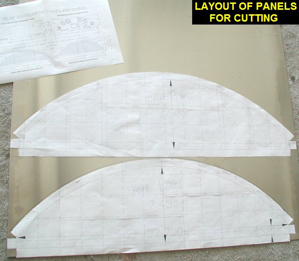
Well I guess I
missed a whole quarter of work on the plane, how lame! I did however
finish some home improvement projects and had a good summer doing stuff
with the kids. Anyway, the last panel I made out of 6061 had a flaw, I
forgot to put the two vertical creases in it before doing the forming. So
unless I can find some dies that fit inside it perfectly, it may stay a
flat panel and unused. I went over to Kens and cut some more 6061-T6 to
make both a new rear panel and a new front panel to replace the 5052 one I
made on 5/18/05. |
 |
| 10/21/05 |
1.0 |
813.4 |
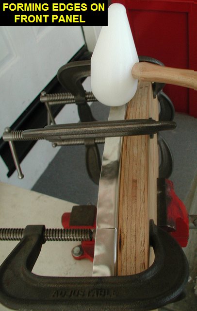
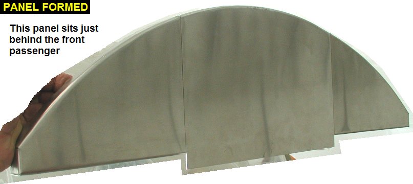
I'm thinking about
doing some of the instrument cutouts in the rear panel before forming it,
so in the meantime I made a new front side panel out of 6061-T6. The other
one made out of 5052 would probably be ok, but since people will pull and
put weight on the panel getting in/out of the airplane I decided to use
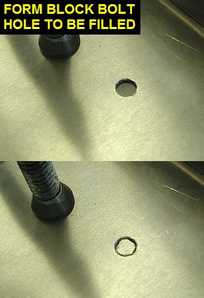
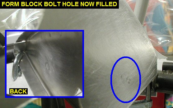
the stiffer material. I also didn't drill holes in the panel for bolt to
go through the forming boards, I just lined up the panel and forms
carefully and used a lot of clamps. The panel came out well with no holes
and didn't shift during forming. |
 |
 |
 |
| 10/27/05 |
1.4 |
814.8 |
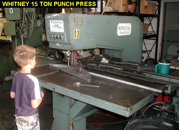
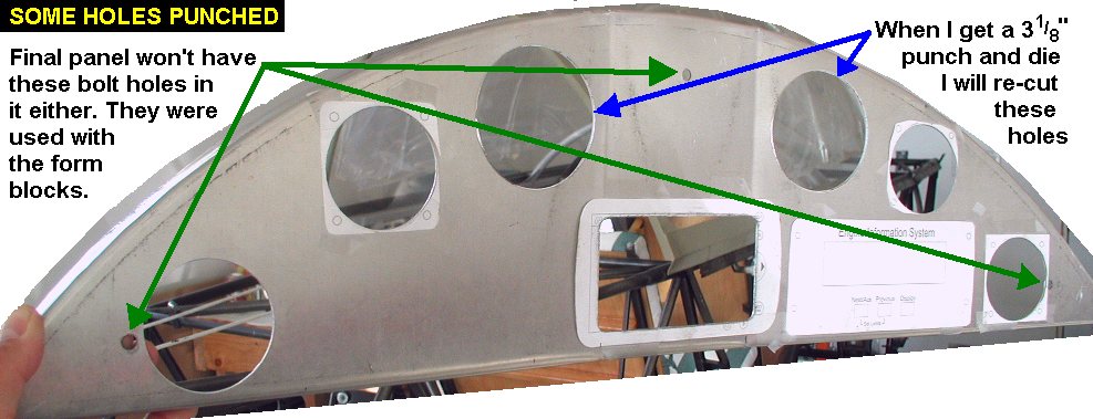
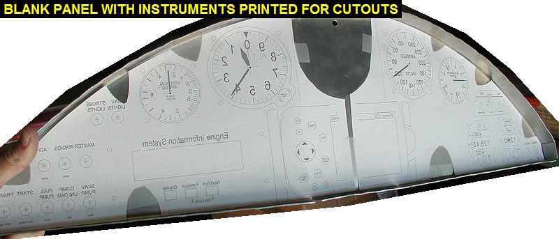
I took
the rear panel blank I got from Kevin and took it over to Ken's to punch
out my instrument holes. I'm using it as a test panel to see how
everything fits etc. I should be able to make a finish panel without the 3
bolt holes for squeezing the panel between the form blocks. Ken has a big
ol' 15 ton Whitney punch press that can punch a 4" diameter hole in
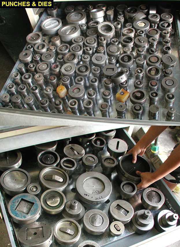
1/4" steel. I did some adjustment to the basic
panel layout I had come up with earlier and then drilled small
centering holes through the panel to line up the dies on. It took more
time to change the dies than it did to punch the holes. The Whitney pops
the holes like a giant paper punch, very clean. Ken had a 2.25" die
and but not a 3.125" so we punched the holes for the big airspeed and
altimeter at 2.875". I was going to cut the two holes out manually
but instead decided to order a 3.125" punch and die for the
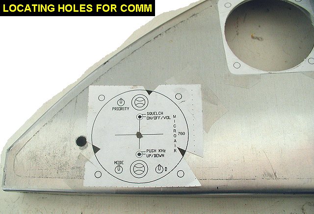
Whitney. When I got home I drilled and fitted the Microair comm
& transponder to fit for testing so I can weld in the forward panel
mounts on the longeron behind the passenger. |
 |
 |
 |
 |
| 11/02/05 |
1.4 |
816.2 |
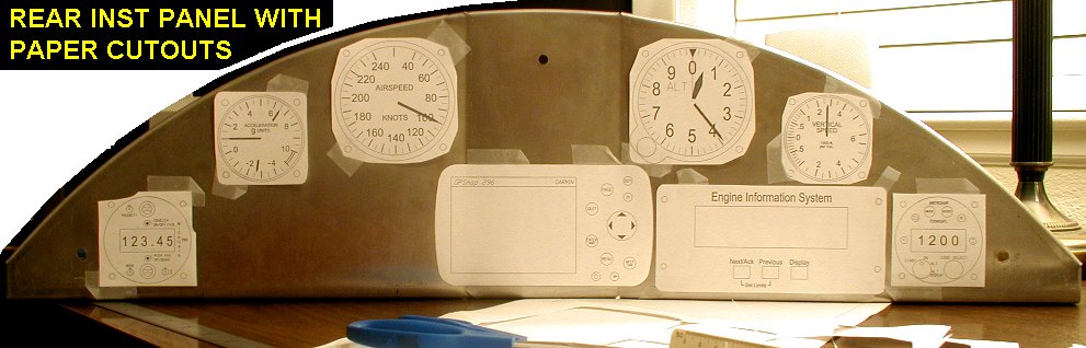
Test
mounted the Microairs in the panel and discovered I have enough room
behind them that I can probably put them both on the left side of the
panel. Spent a bunch of time on my layovers trying different layouts in
the computer, see RearInstPanel051102.pdf.
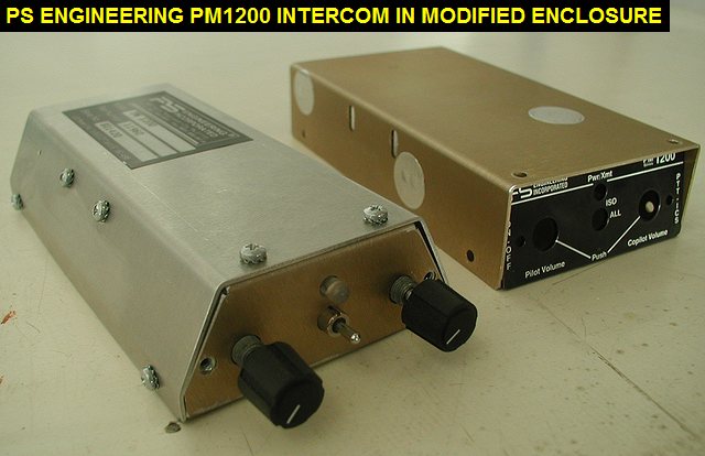
I also discovered that the PS-1200 intercom I have would fit better up
close to the edge of the panel if it didn't have a rectangle cross
section. Upon disassembly I found that I could make a new cover for it in
a trapezoidal shape and put it above the microairs. So I drew up and made
a new cover for it, see PS1200Lid_051102.pdf.
I used a heat gun to carefully remove the sticker from the old case for
the new one. |
 |
 |
| 11/07/05 |
4.3 |
820.5 |
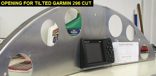
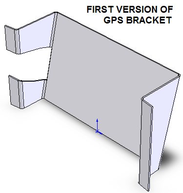
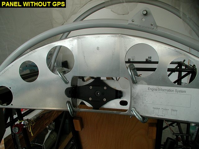
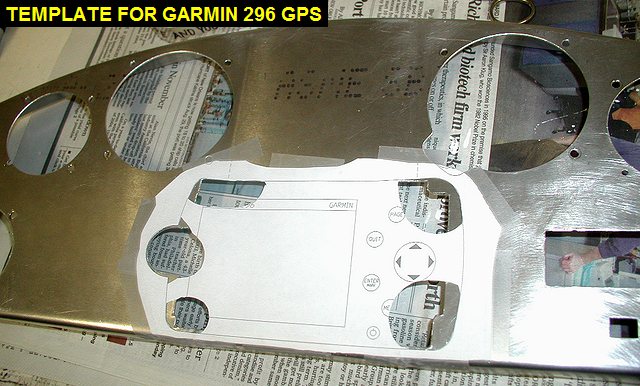
I
realized that I had better figure out a way to mount the Garmin 296 before
I go further with panel layout. I want to make it easily removable for
other use, and also mount it tilted up towards the pilot for best viewing
quality in bright sunlight. I can use part of the included Garmin yoke
mount that holds the GPS unit along with a sheet metal bracket mounted to
the back of the panel. I found it very difficult to model the GPS, panel
and bracket in the computer, and it took a couple hours to come up with a
drawing. I will make a prototype to see how it fits, hoping not too much
trial and error will be required to get it right. I also spent some time
making the hole for the GPS in the panel. |
 |
 |
| 11/11/05 |
4.0 |
824.5 |
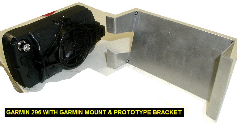
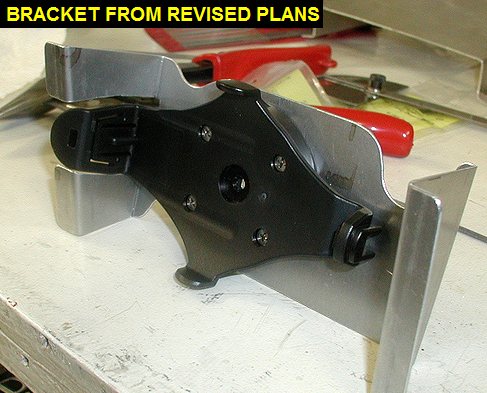
The prototype was
pretty close, but it had the GPS sticking out a bit too much. After
sitting in the cockpit playing with it in position using shims I came
figured out how to modify it. I also decided to make the left
"leg" of the bracket about .1" longer so the GPS screen
tilts slightly right, aiming perfectly at the pilot. This is because the
screen is on the left side of the GPS case and the button pad on the right
is raised slightly. Another change was to shorten the overall height of
the bracket. After making the changes to the drawings, I went over to Kens
and cut/bent up another one. |
 |
 |
| 11/12/05 |
2.3 |
826.8 |
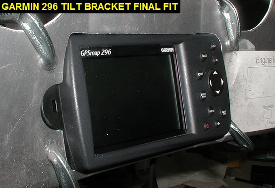
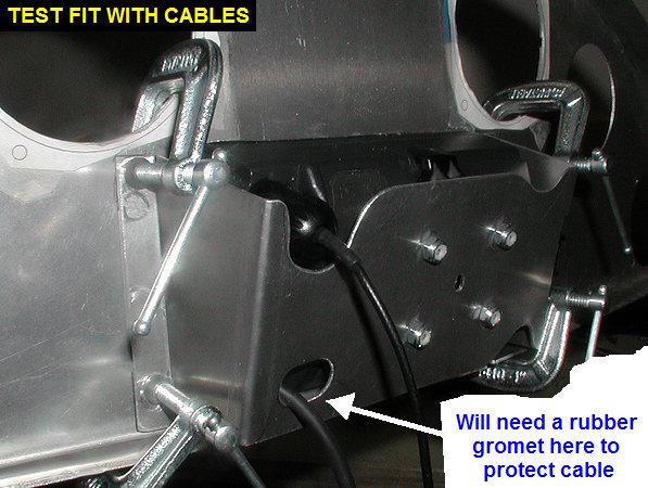
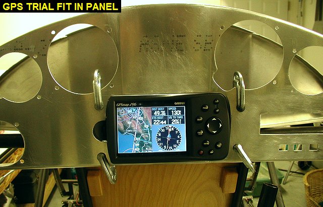
This
bracket is just about perfect. I spent some time locating and drilling the
holes to install the Garmin mount to the bracket. Then I did some minor
panel trimming for better fit of the GPS. I also had to enlarge the panel
opening slightly in a few areas to allow the GPS to be inserted and
removed from the front of the panel. I then cut some relief areas to allow
my fingers to push the GPS out of the panel from behind when the catch is
released. I also cut relief for the antenna and power cables. Right now I
just hold the braket on the panel with C-clamps, I need to order some 6-3
compact nutplates to put on the bracket so I can screw in onto the
instrument panel. |
 |
 |
 |
 |
| 11/13/05 |
2.4 |
829.2 |
I traced my hole
pattern and relief cutouts back onto my paper pattern. Using my dial
calipers I then measured them out and added them to my computer model of
the bracket. Here is the final drawing of the bracket G296TiltBracket.pdf.
Next I will make a drawing of the panel cutout needed. |
 |
| 11/28/05 |
2.0 |
831.2 |
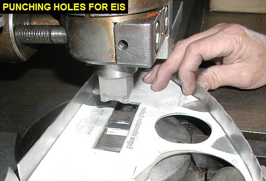
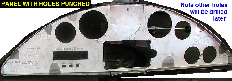
I
printed a mirror image of my panel design and cut it out to fit inside the
back of the panel. Armed with that, another blank panel, and my new 3.125
punch and die, I went over to Ken's. We put the two vertical bends in the
panel and then punched the holes for the instruments. We were also able to
get the holes pretty close for the EIS by using successive smaller
rectangular punched holes. |
 |
 |
 |
 |
| 11/29/05 |
1.5 |
832.7 |
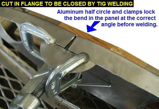
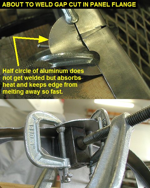
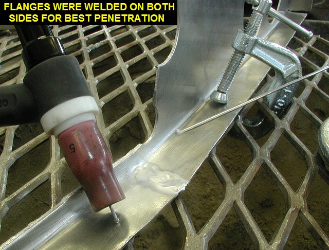
The
instrument panel is pretty flimsy right now with all the holes and cuts in
the flanges, so I decided to weld up the cut flanges of the instrument
panel to stiffen it up. I did some practicing on the scrap panel cut outs,
cutting them in half and then welding them back together. Using a .040
pure tungsten, AC and a 55 amp max setting, I was able to do a decent job
with my Lincoln Precision TIG 275 welder. I clamped a steel block in place
below the gap to hold a small pie shaped sliver of aluminum and also keep
the weld bead from sagging while welding. After welding both sides of each
cut flange, I'll only have to do a little cleanup with the die grinder and
file. The panel is really strong now. I may even weld up the corners of it
two once I get them adjusted. |
 |
 |
 |
 |
| 12/02/05 |
0.7 |
833.4 |
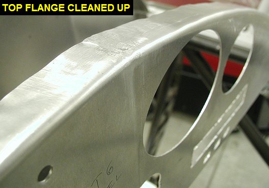
Used a die grinder,
files and sandpaper to clean up the welded areas on the rear instrument
panel. |
 |
 |
| 12/08/05 |
1.8 |
835.2 |
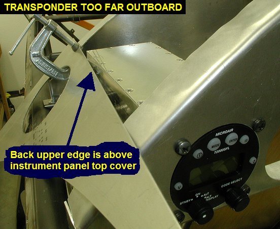
I drilled the
necessary holes to mount the microair transponder and promptly discovered
that I had moved the radios too close to the end of the panel. The forward
upper corner of the transponder will interfere with the sheetmetal that
goes over the top of the panels. Oops! I fired up the computer and moved
the two microairs inboard about 3/8" which made RearInstPanel051208.pdf.
I then made a another panel blank with another flat piece .050 6061-T6 in
my wood forms. Hopefully the 3rd one will be a keeper! I am getting better
at making them though. |
 |
| 12/09/05 |
2.0 |
837.2 |
I printed out a
mirror image of my newest panel layout and went over to Ken's for
essentially a repeat of 11/28/05. We did a nicer job cutting the holes for
the EIS by setting the backstop on the punch, that way all multiple punch
operations stayed in a nice straight line. On the 28th we freehanded them. |
| 12/15/05 |
3.0 |
840.2 |
Test mounted the
transponder to make sure it will clear the top sheetmetal, which it will.
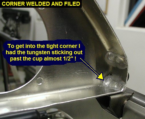
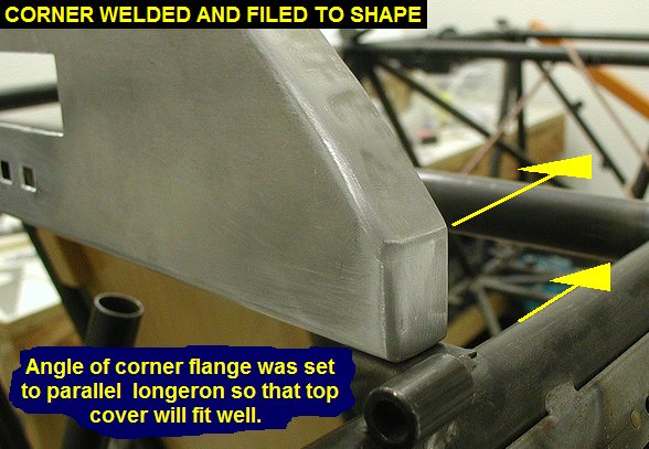
I then welded up the cuts in the flange at the bends. Then I adjusted the
end flanges to allow a good fit of the top, then welded up the corners of
the flanges, running beads on both sides of the joints. After that a
little file work was needed to make nice looking corners. The panel is
really strong now. |
 |
 |
| 12/15/05 |
1.5 |
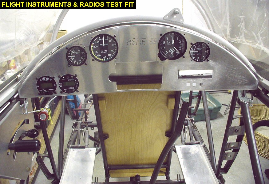
841.7 |
Spent some time
drilling holes and filing holes as needed to mount the flight instruments
and radios for a test fit. |
 |
 |
| 12/30/05 |
2.0 |
843.7 |
Printed out another
drawing of the Garmin 296 and taped it onto the panel so I could figure
out where to remove aluminum. I took my time and got the GPS fitting well,
and able to be removed/installed through the front of the panel. There is
a little gap between the GPS and the panel, which allows it to tilt as it
comes out, but the gap isn't too noticeable. |
 |
 |
| QTR TOTAL |
34.2 |
|
|
4TH QTR 2005
|
•
•
•
|


