|
1ST QTR 2006
|
 •
•
 •
•
 •
•

|
| DATE |
HRS |
TTD |
ACTION |
IMAGES |
| 01/01/06 |
2.5 |
846.2 |
Did some design work
for a box that will attach to the back of the front seat. It will have a
top face suitable for switches or circuitbreakers, and will have a case
that will open to hold charts etc. Shown at right is the basic box, I
still have to design the case that goes in the rectangular hole. |
 |
 |
| 01/02/06 |
2.0 |
848.2 |
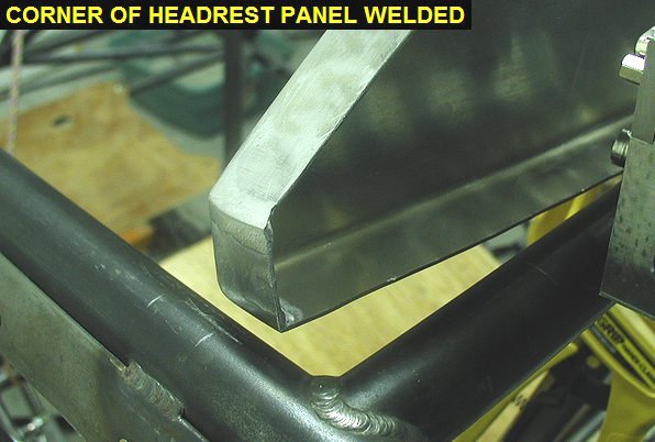
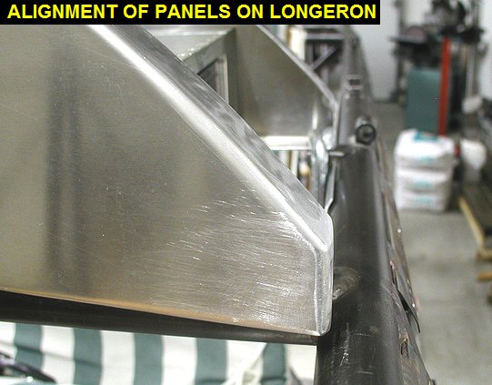
Removed the canopy
so I could work on fitting the passenger headrest panel. I adjusted the
angles of the flanges and then TIG welded the joints and corners up. I
also filed them to shape. |
 |
 |
| 01/03/06 |
2.5 |
850.7 |
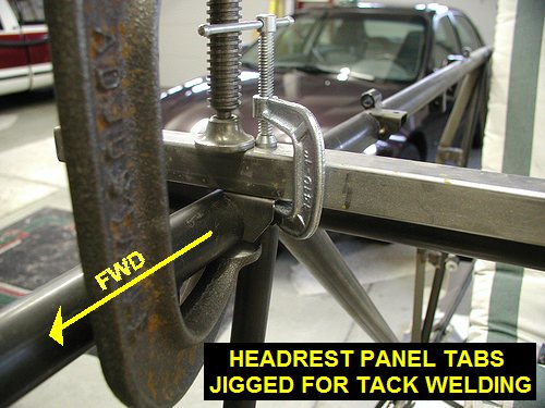
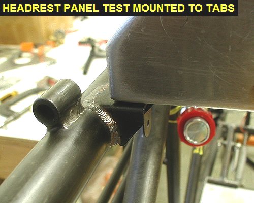
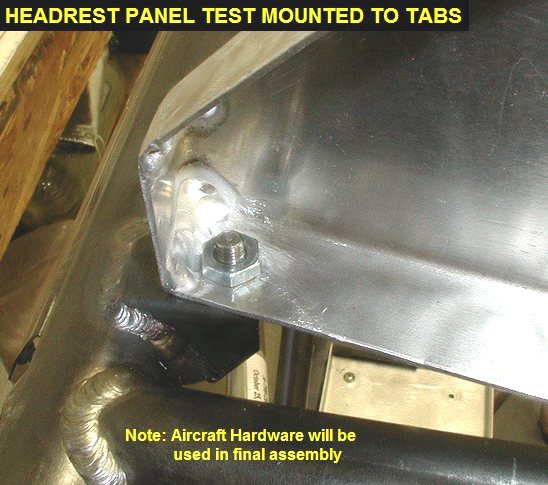
Located and jigged the tabs to
mount the headrest panel, then welded them in. I also welded in the rear
instrument panel tabs. I then located and drilled the holes in the panels
for the 10-32 bolts or screws to mount them. |
 |
 |
 |
 |
| 01/19/06 |
1.0 |
852.2 |
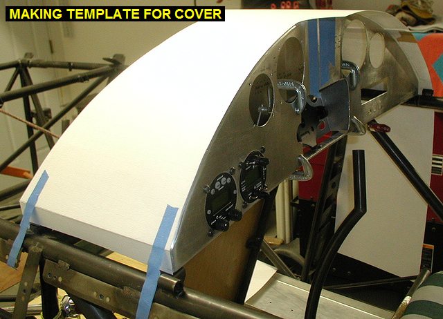
Got some posterboard and used it
to make a template for the instrument panel top cover by taping it into
position and progressively marking and trimming it to size. |
 |
 |
| 01/20/06 |
1.5 |
853.7 |
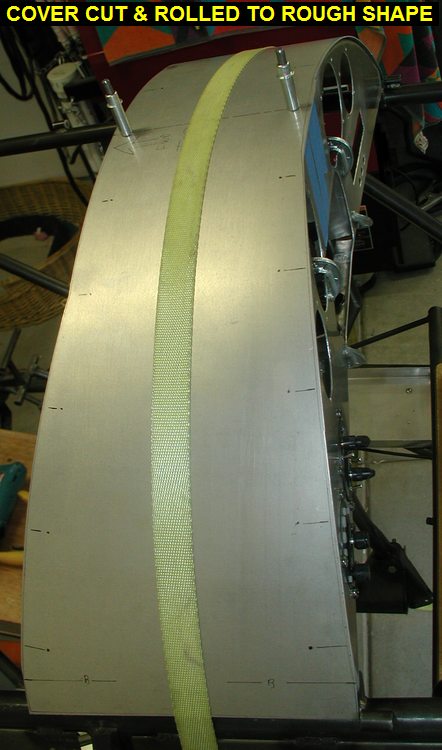
I traced the posterboard outline
onto some .050 6061-T6, then went over to Kens and cut out the cover. I
used the slip-rolls to get it rolled into the basic diameter needed. |
| 01/26/06 |
2.5 |
856.2 |
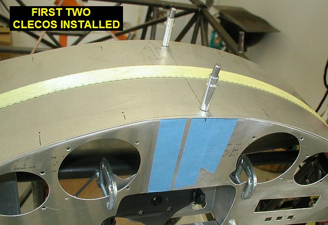
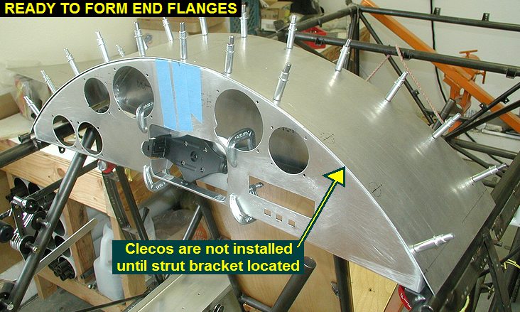
With a tie-down
strap holding the cover tight against the panels, I positioned the cover
and drilled two #40 holes for clecos in the center of the arc. I then
spaced out the holes 3" on the back panel and 3.1" spacing on
the front cover and installed silver clecos. I then used a sharpie pen to
mark where to trim the panel, and did so. |
 |
 |
 |
 |
| 01/27/06 |
1.0 |
857.2 |
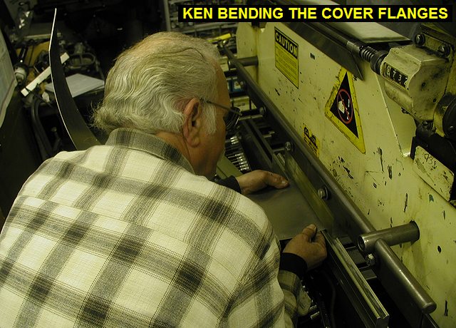
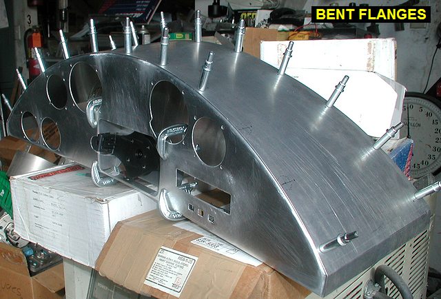
Went over to Ken's and bent the
flanges in the outer edges of the cover. |
 |
 |
 |
| 01/30/06 |
4.0 |
861.2 |
Drilled, clecoed and then
installed 6-32 nutplates on the Garmin 296 bracket. It will attach to the
panel with instrument screws. Worked on fitting the cover, but eventually
did a canopy test fit. Arghhh! The front panel is too wide and tall. I
thought I had enough room, but didn't test the canopy in the forward
locked position until tonight, assuming it slid parallel to the longerons.
Its obvious now that the gap between the canopy and the instrument panels
is tightest when its forward and locked. I'm not sure what I'm going to
do, and I hate learning this way. |
 |
| 01/31/06 |
6.0 |
867.2 |
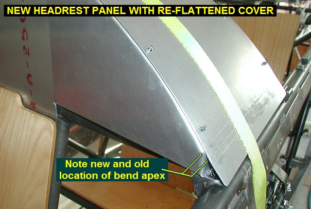
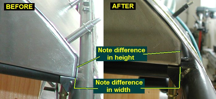
I decided to make a
new headrest panel, figuring it needed to be about 3/16" narrower on
both sides, and profile down lower about the same amount at the ends too.
I cut and reshaped my oak form block, then pounded out a new panel. I then
took it over to Kens and put the two vertical bends in it. I was going to
make a new top cover, but Ken suggested I flatten the flanges and re-bend
them. I was able to flatten the flanges using a polished rivet bucking bar
and a smooth surface ground piece of steel plate to keep from putting
marks in the cover. I then annealed the bend area to keep it from cracking
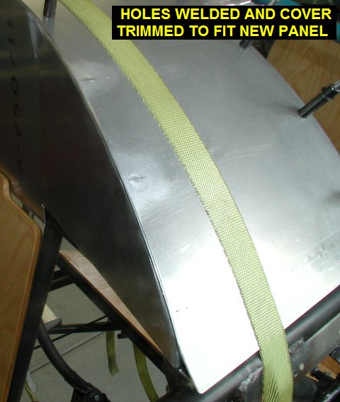
on the next bend. I then discovered that the cover fits the new panel
differently, putting the outer holes in the cover too close to the edge of
the new panel, so I welded them up. |
 |
 |
| 02/01/06 |
2.0 |
869.2 |
Drilled and clecoed the new
holes in the top cover, and trimmed it to fit the panels better. I then
took it over to Kens and re-bent the edge flanges. Yea! The canopy will
now close over my sheetmetal work. Here's the updated
drawing for hammerforms to make panels that work. |
 |
 |
| 02/07/06 |
2.5 |
871.7 |
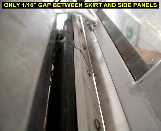
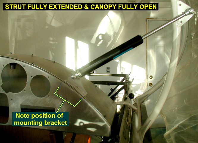
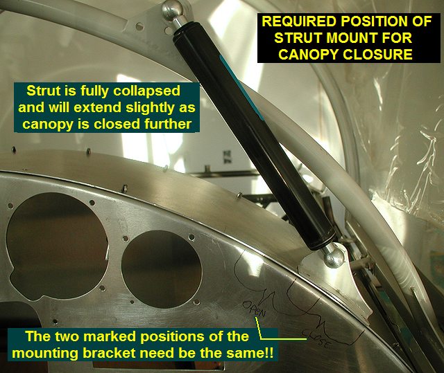
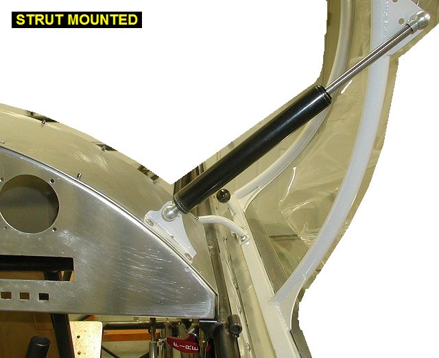
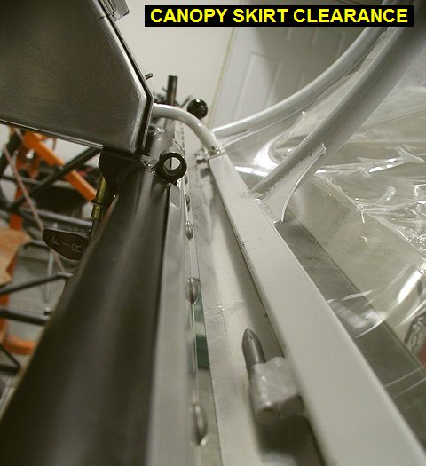
Spent a lot of time
trying to get the canopy damper strut and mount for it figured out. I have
determined that my sheetmetal must be slightly wider than a Kimball
fuselage probably because I put my side formers on a little differently.
Thus my canopy cannot open quite as much before the skirt hits the
aluminum side panels. I shortened the ball joint sockets on the strut to
shorten it as much as I dared but still could not get the strut to work.
Canopy and hinge geometry makes the strut reach its minimum length about
1/3 open, and if I put the strut bracket in a position where the canopy
will close, it then allows the canopy to open way too much and hit the
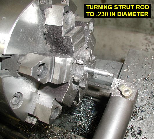
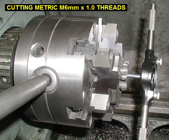
sheetmetal. I need a strut that doesn't extend quite so much! Looking at
pics of N80XP I think they had the same problem and solved it with a cable
limiting the travel of the strut and canopy, but tomorrow I will go over
to Kens and see if we can cut the strut down on the lathe, and then
re-thread the end with a M6x1 die. |
 |
 |
 |
| 02/08/06 |
3.0 |
874.7 |
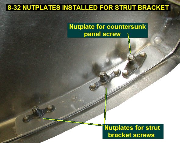
Went over to Kens
and made the strut about .570 shorter than it was before. Came home and
figured out where to mount the bracket on the panel. I then made a small
doubler plate to put between the nutplates and the instrument panel
flange. I then put the nutplates in. After testing it in its new mount I
decided to order another strut, when I get it I will cut it down more so I
can leave the ball joints with more material. I am concerned I have taken
too much material off these ones in my first attempts to fit it. |
 |
 |
 |
 |
 |
 |
| 02/15/06 |
1.0 |
875.7 |
I got my new strut and determined that it
was possible to shorten the strut in the lathe and not modify the
balljoints whatsoever. Another trip over to Kens and I made the shaft
1.15" shorter which gives the strut a 3.0" stroke since it
collapses all the way to the balljoint base. See
drawing Of Modified Strut |
| 03/08/06 |
1.5 |
877.2 |
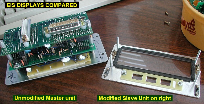
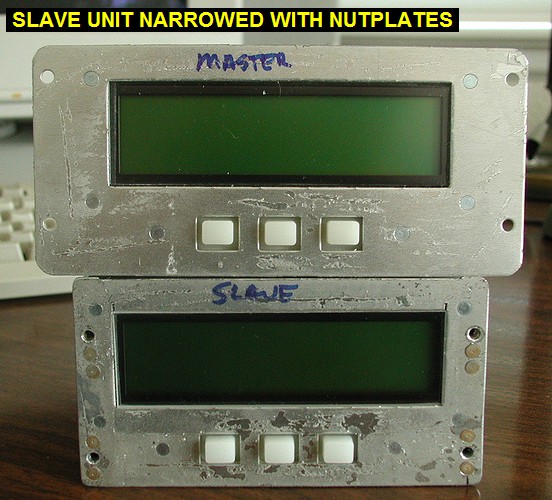
Life intervenes again! I find
myself involved in another home improvement project, this time my office.
I'm emptying it out for hardwood floor, built-in cabinets and countertops
so it will look as nice as the rest of the house. I don't know why my wife
can't stand my office, I know EXACTLY where everything is. Anyway, I
needed to figure out how to narrow the EIS display boxes so I can fit
stuff closer to them in the panels. So I took them apart for investigation
and decided I could install nutplates just inside the cover, then trim off
the mounting flange extending outside the cover. |
 |
| 03/08/06 |
3.5 |
880.7 |
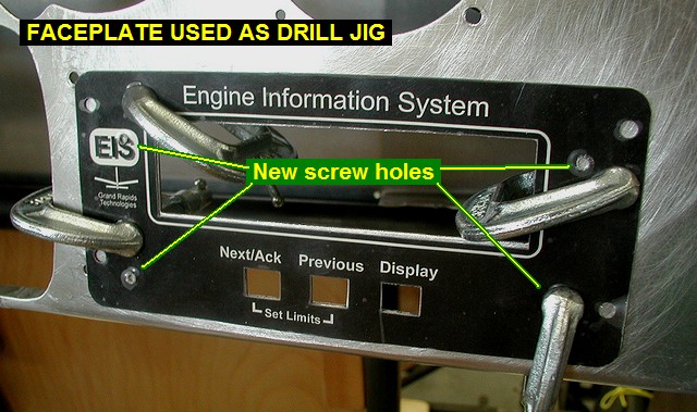
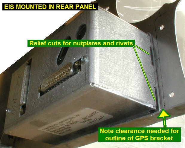
Since I will be
mounting my EIS boxes behind my panels I had pulled off the decorative
faceplates so I could use one as a template to keep them on identical
screw patterns. Note that I always kept one EIS assembled so I could see
how to put the other back together! I also put masking tape over the
display screen to keep it from getting scratched while drilling etc. After
installing the 6-32 nutplates, I had to do some minor trimming of material
from the back covers to allow them to fit tight without hitting the
nutplates or rivet shop heads. Using the faceplate as a template I drilled
holes and test mounted the EIS. Looks good and won't hit my GPS bracket
now. |
 |
 |
 |
 |
| QTR TOTAL |
36.5 |
|
|
1ST QTR 2006
|
•
•
•
|