|
2ND QTR 2005
|
 •
•
 •
•
 •
•

|
| DATE |
HRS |
TTD |
ACTION |
IMAGES |
| 04/20/05 |
1.5 |
794.4 |
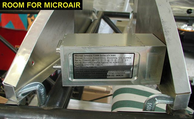
Back to work! Why am I
working on the rear instrument panel????? To start out I need to
locate the rear instrument panel mounting tabs on the fuselage. The rear
ones are already tacked in, but the front side of the inst panel, that goes right
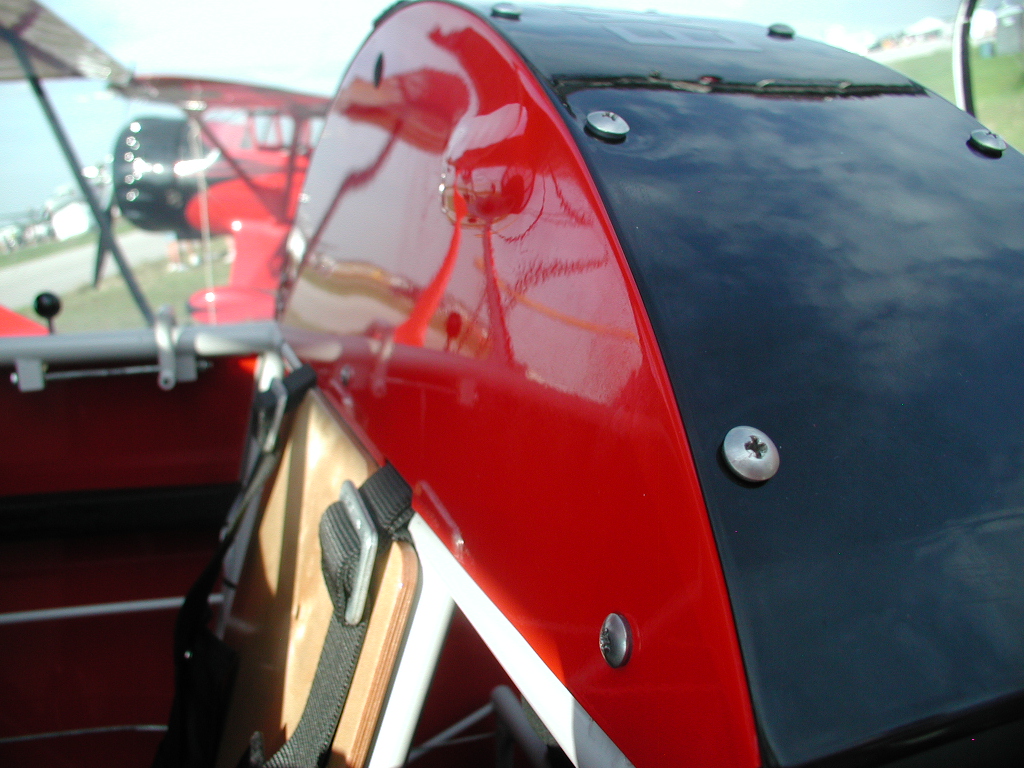
behind the passengers head is a little more complicated. Kevin normally
mounts that panel flush with the crossmember and at the same angle of the
seat back, see pic. I
plan to use Microair
radios which are a little longer than the panels allow, so I have to
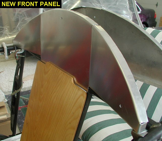
move the forward panel out a little on the sides to make room. Rather than
making some sort of pop-out
I decided to have that panel come forward from just outside of the
shoulder harnesses, kinda like the rear panel but opposite.
So...I'll need to use a couple of tabs on the longerons just like the rear
panel, but need to figure out where they go. I've also decided to get the
panels made up and assembled so I can get the canopy lift strut installed
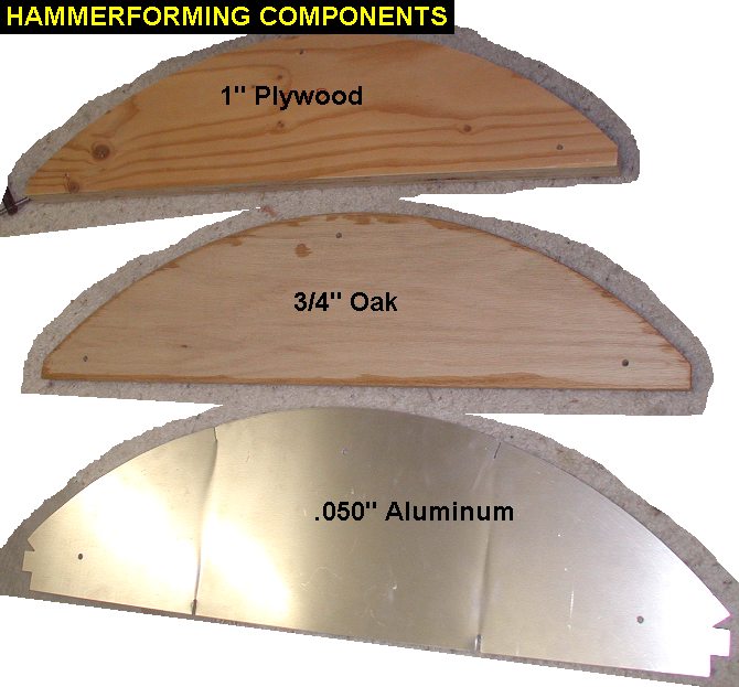
and working. To start out I drew out the front panel in Autocad, then
plotted a pattern to make two hammerforms. I'm making my own rear inst
panels because I want them bent a little differently than they came from
Kevin, plus I want to be able to make spares as needed. |
 |
| 04/28/05 |
1.5 |
795.9 |
Cut out the rough plywood forms
and .050 6061 sheets over on Ken's bandsaw. I then used my oxy-acetylene
torch to anneal the aluminum sheet, what a mistake! The heat totally
warped the material and its pretty useless. I called Jimmy for advice and
he offered some 5052 which would be soft enough to work with without
annealing. |
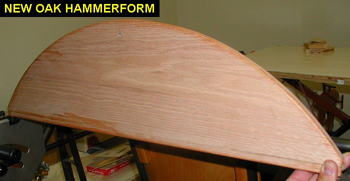
| 05/05/05 |
1.0 |
796.9 |
Cut a new hammerform out of oak
which will stand up better. Also sanded a 7 degree overbend into the
pattern to allow for springback of the aluminum. |
 |
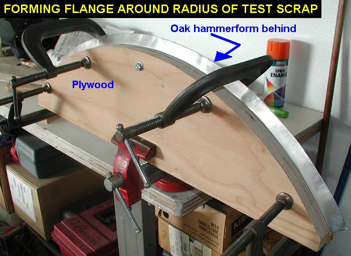
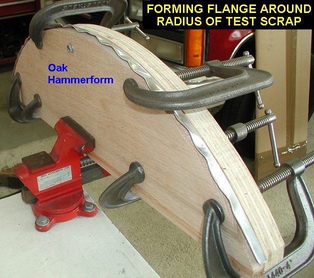
| 05/06/05 |
3.5 |
800.4 |
Made a visit to see
Jimmy to pick up the 5052. There I learned that the two panels I got from
Kimball Ent were made out of 6061-T6 which they must have formed over a
steel hammerform without annealing. After I got back I used a piece of
scrap 5052 to do a test run with the oak hammerform. With some patient
work I was able to get a decent looking flange bent into the panel. Also I
ended up increasing the spring back allowance to 9 degrees in the oak
hammerform to get a nice 90 in the flange. However I discovered that
there's some difference between the front and back panels that make up the
rear instrument panel assembly. The rear panel is .35" lower at the
height of the radius than the front panel. I need to get Kevin's advice,
before I proceed. |
 |
 |
 |
 |
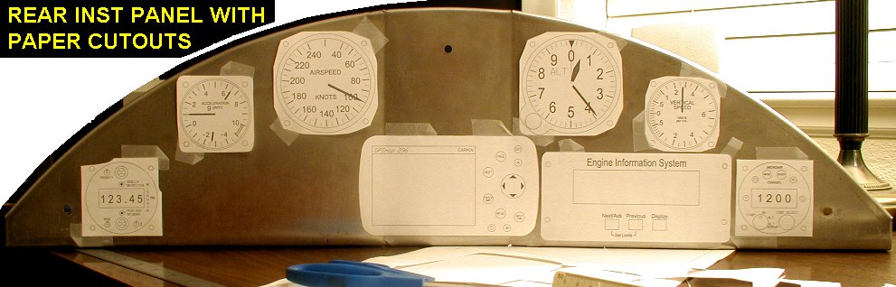
| 05/12/05 |
3.0 |
803.4 |
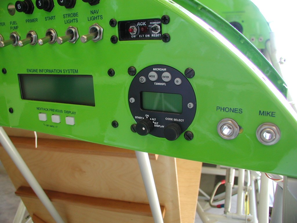
Took all my radios &
instruments on my Maui layover and drew them all into autocad. Came home
and plotted them out full scale so I could get an idea what my panel
layout might look like. Regarding the question of the two panels, they are
different in height because the front panel is leaned back like the seat.
I've decided after sitting in there, that having it vertical will not be a
problem and they both can have similar heights, but I need to make two
hammerform patterns because the forward panel will be slightly wider to
match the longerons. I then reinstalled the canopy so I can design my
hammerforms to make panels that work with the canopy exactly like the
Kimball panels do. See
rear instrument panels drawing here. (3/7/07 - See final
version of this drawing) |
 |
| 05/17/05 |
3.7 |
807.1 |
Did several
measurements on the areas where the panels go and then revised my rear
instrument panels drawing. I plotted them out full scale using my
laser printer, which took many sheets of paper cut and taped together,
then went over to Ken's and sawed new hammerforms and aluminum blanks with
his nice big band saw. After sanding in the extra 7° of bend into the oak
forms I then applied cyanoacrylate glue to the edges to harden the wood
and increase its resistance to compression. Kevin says to use 6061-T6 on
the panels and only anneal the edges, but I'll do that later, I'm going to
make some blanks first with the softer 5052 that Jimmy gave me. I suspect
the 5052 panels will hold up ok as long as I never let 250lb guys pull
themselves out of the rear seat with the panel alone. Hopefully I'll be
able to make panels out of both materials before my hammerforms get too
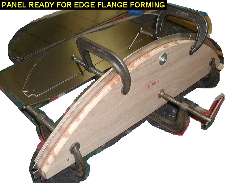
hammered. I loaded the fwd panel in and got it ready to go, but didn't
think it wise to start hammering away in the garage at midnight. |
 |
 |
| 05/18/05 |
2.0 |
809.1 |
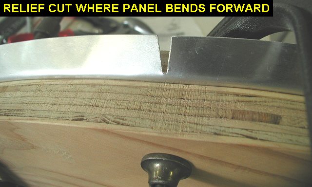
Cut relief into the
flange where the panel will be bent forward, then formed it over the oak.
Note that I left the panel flat in the area of the front seat backboard. I
will have to make cutouts for the shoulder harnesses there and didn't want
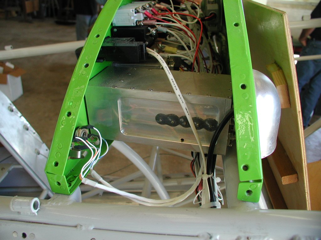
a flange interfering. After forming the panel I test mounted it to see how
far forward the bend would have to go to allow room for the radio and
transponder. I sat in the front seat and found that even without a back
cushion the vertical panel didn't bother me, still I didn't weld the tabs
on the fuselage yet, I want to think about it for a couple days. |
 |
 |
 |
 |
| 05/05/05 |
1.8 |
810.9 |
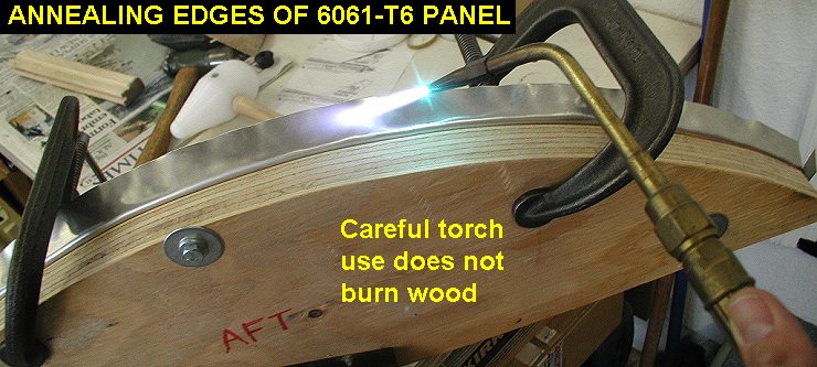
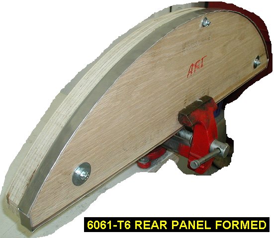
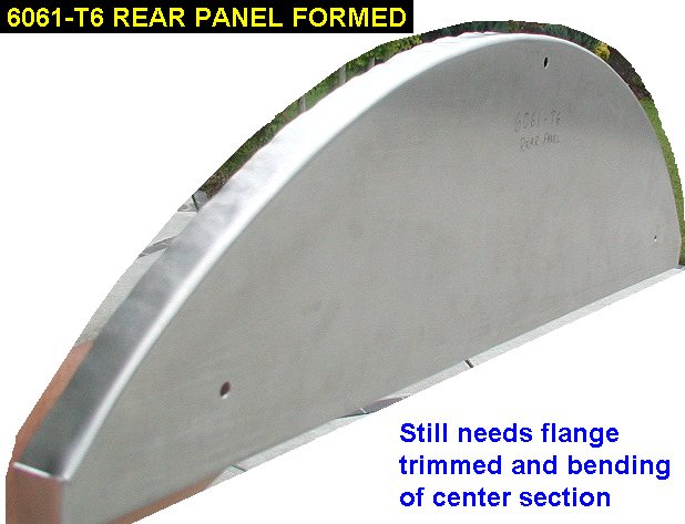
Got out the 6061-T6, the rear
panel hammerforms and the oxy-acetylene torch and went to work forming the
rear panel. I could really tell the difference in ease of forming the
aluminum after annealing the edge each time. I heated the edges once
before starting to pound on it and then 2 other times before finishing, I
was also able to do it without burning the wood. The oak form looks pretty
good afterwards, I can't see any crushing yet. |
 |
 |
 |
| QTR TOTAL |
XX.X |
|
|
2ND QTR 2005
|
•
•
•
|


