|
3RD QTR 2008
|
 •
•
 •
•
 •
•

|
| DATE |
HRS |
TTD |
ACTION |
IMAGES |
| 08/18/08 |
2.0 |
989.9 |
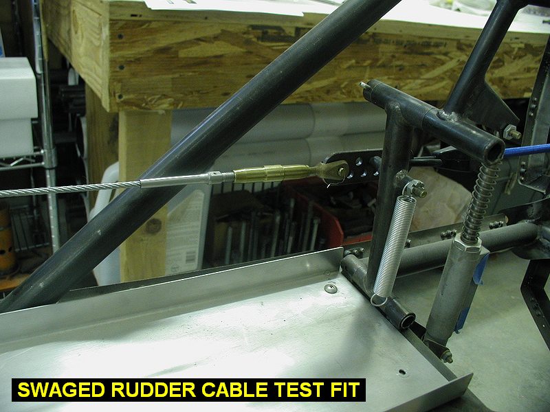
Cleaned up the garage so I could
work again. I want to work on getting the rudder pedals working in the
front cockpit. Took off the firewall and installed the rudder. I got out
the cables that Kevin had swaged for me awhile back and installed them to
the rear pedals. I found that one of the MS 21259-4RH stud ends would not screw into either of the AN155-32S turnbuckle barrels I had without excessive force using hand tools. It was obviously cutting brass inside the barrel. The other cable's stud worked fine screwing in by hand. It was like the stud threads were too big so I ran a 1/4-28 die down it part way and tested the fit. It would then fit fine in the barrel up to the point I stopped with the die.
Wierd. I then decided to run the die all the way down, but the SS stud thrashed my die which then started cutting the points off the threads of the stud on the way back up. So now that cable assy is scrap (way too loose fit now) but can still be used for fitting purposes so I can make the tie rods between the pedals. I'll
just have to have another cable assembly made sometime in the future. |
 |
| 08/27/08 |
1.8 |
991.7 |
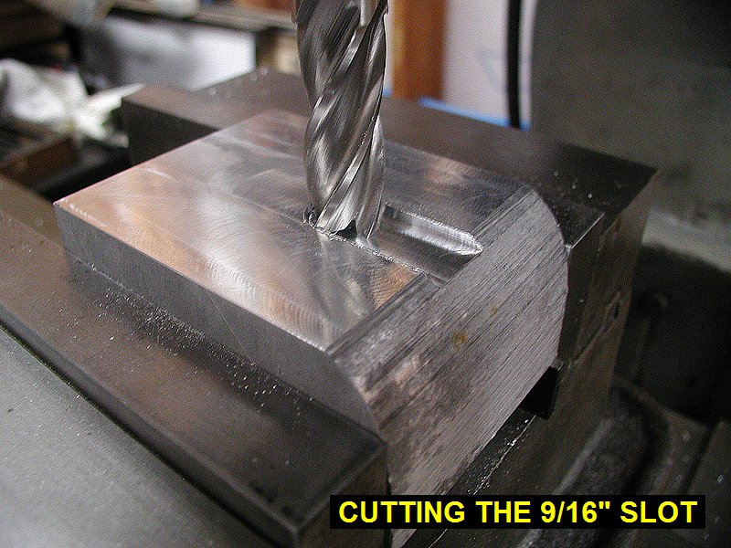
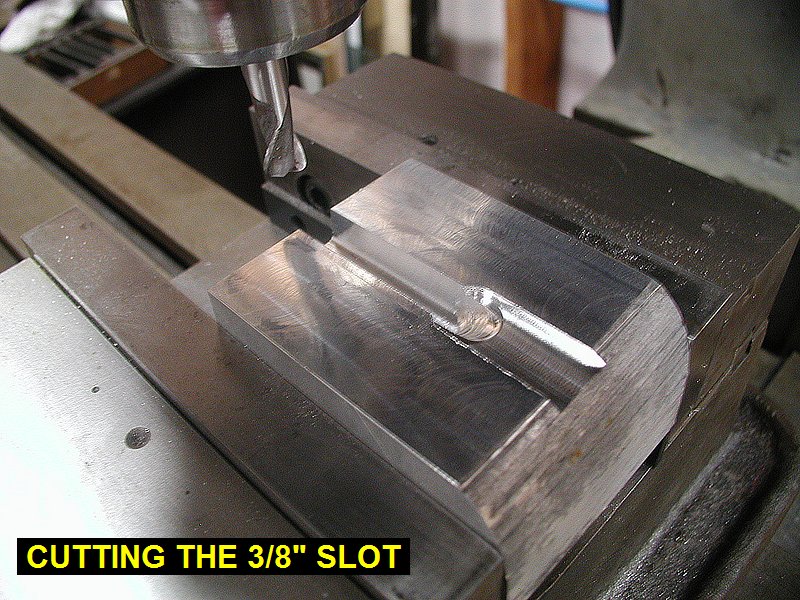
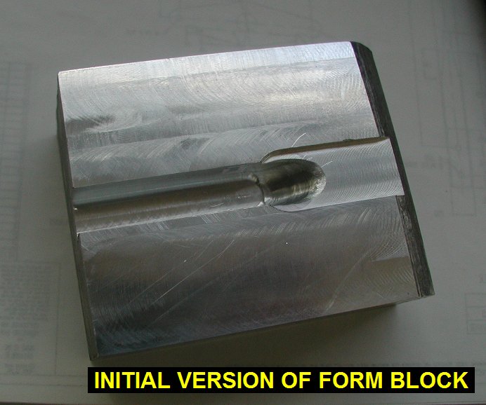
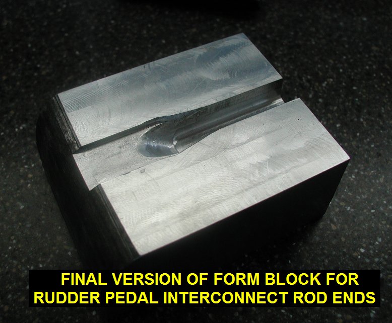
Worked on making an aluminum form block to
make the 510-45 Rudder Pedal Interconnect Rods.
Did a quick drawing in autocad and then milled out a block with two slots,
one 3/8" wide and deep, the other 9/16" wide and .072"
deep. Used a 3/8" ball shaped carbide burr in the mill and made the
transition between the rod and the flat area. |
 |
 |
 |
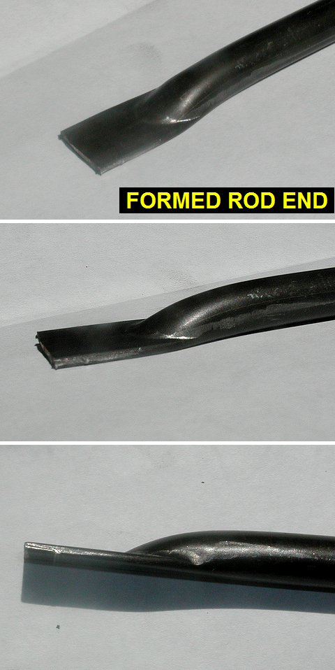
| 08/28/08 |
1.7 |
992.4 |
Radiused the transition area out further
with a hand file. Went over to Dons and did a test press in his hydraulic
press. Took more material out of the form block using a dremel tool until
it made nice rod ends as shown. Works great! |
 |
 |
 |
 |
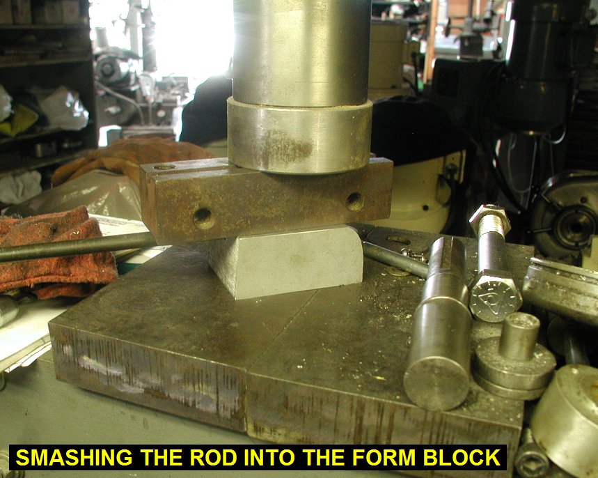
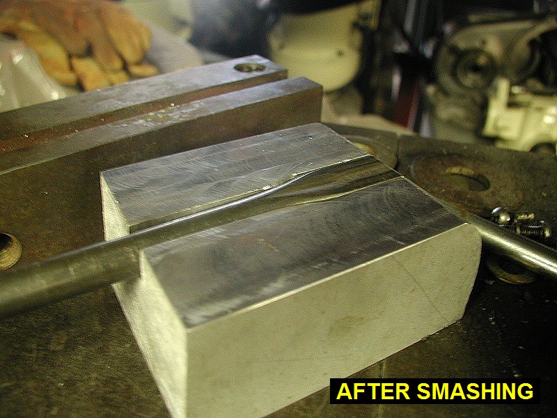
| 08/29/08 |
2.8 |
995.2 |
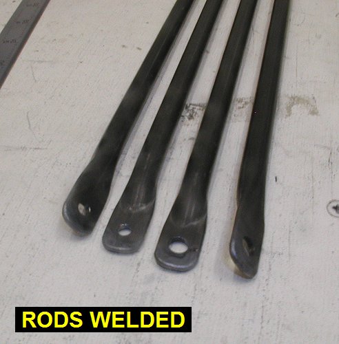
Measured and cut the 4
interconnect rods and then went over to Don's and smashed them. Then came
back and put 3/16" holes in two of them for the brakes, and 1/4"
holes in the other two for the rudder pedals. The rods were cut to
32.1" and then the holes were centered 0.4" from the ends. |
| 08/30/08 |
1.0 |
996.2 |
Rounded the corners of the 4
interconnect rods then welded up the edges. |
 |
| 09/05/08 |
1.5 |
997.7 |
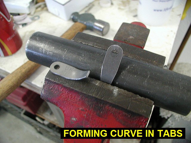
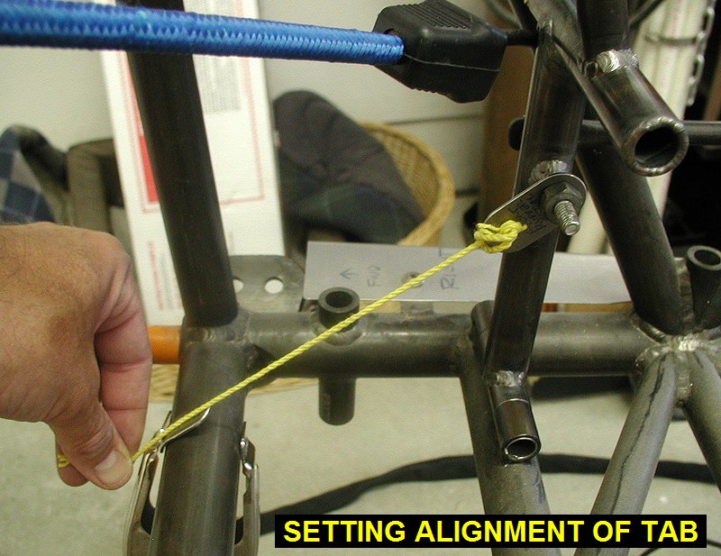
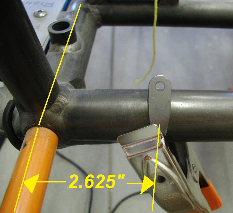
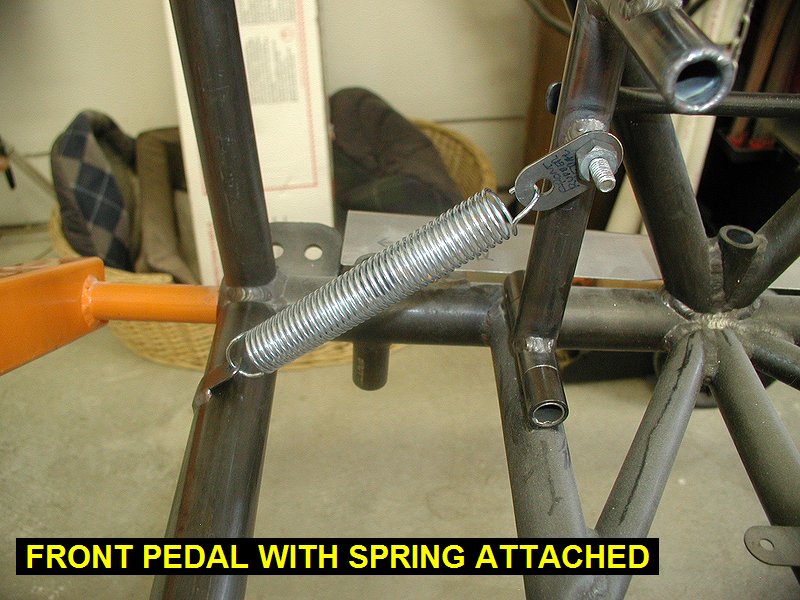
Formed a curve in the Rudder Spring Tabs to
fit the 210-24 crossmember. I then located then 2.625" inboard from
the lower longeron centerline, and at an angle meeting the forward pedal
spring attach, then welded them in. I then installed Century
Spring CSC Stock Number 79 springs (.75 OD x 3.5 Between hooks with
.062 wire) which were the best fitting springs I could find at my hardware
store. They seem to work well. |
 |
 |
 |
 |
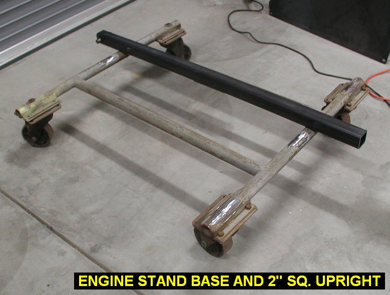
| 09/19/08 |
2.5 |
1000.2 |
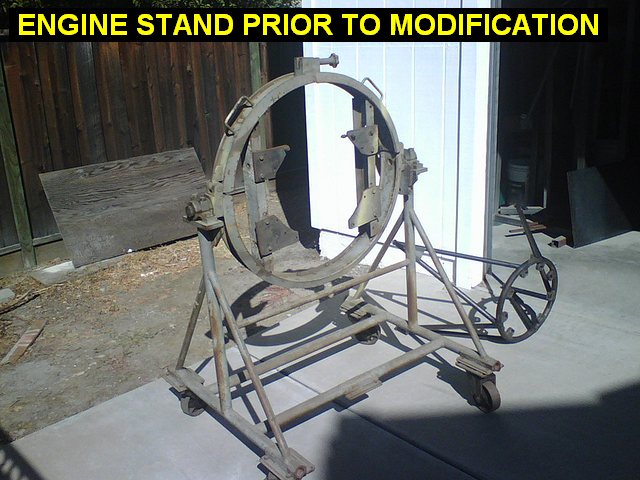
I inherited an old radial engine stand, and
decided to modify it to hold my firewall forward / engine package. I used
my sawzall to cut the existing structure off it. I bought some 2x2x.1875
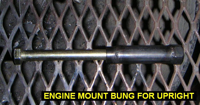
wall square tubing to hold the motor mount. I also made 4 bungs to bolt
the motor mount to, welded up from a 1/2" section of .75x.12 tubing,
3" of 1/2" steel pipe with a 1/2" course nut welded on the
end. |
 |
 |
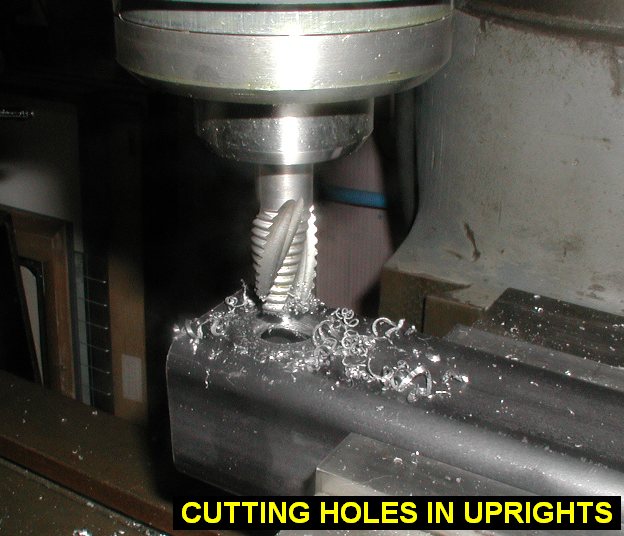
| 09/20/08 |
1.4 |
1001.6 |
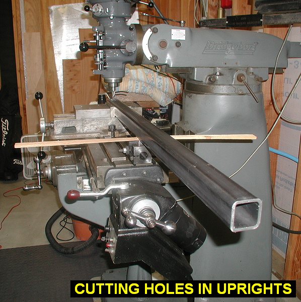
Cut the top 7/8" hole in
one of the engine stand uprights where the bungs will weld in. I first
located and drilled 1/4" all the way through the 2" upright.
Then using 5/8, 3/4 and finally 7/8 endmills, enlarged the hole on
each side of the upright. |
 |
 |
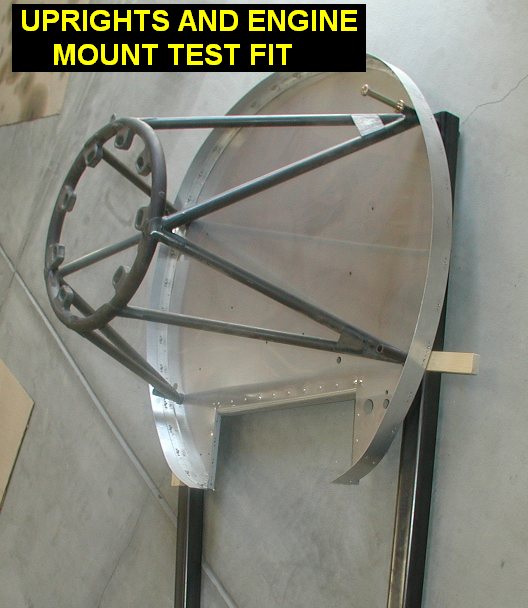
| 09/21/08 |
1.4 |
1003.0 |
Cut the top hole in the other
upright. Dropped the bungs in the top holes and test fitted the fwf/enginemount
to see how it looks. I may not use a bung on the bottom holes since they
will be loaded in compression only. Although we sometimes get earthquakes,
no negative G's for the engine stand are expected!! |
 |
 |
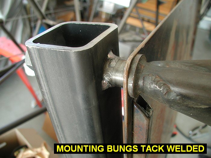
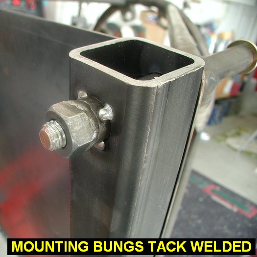
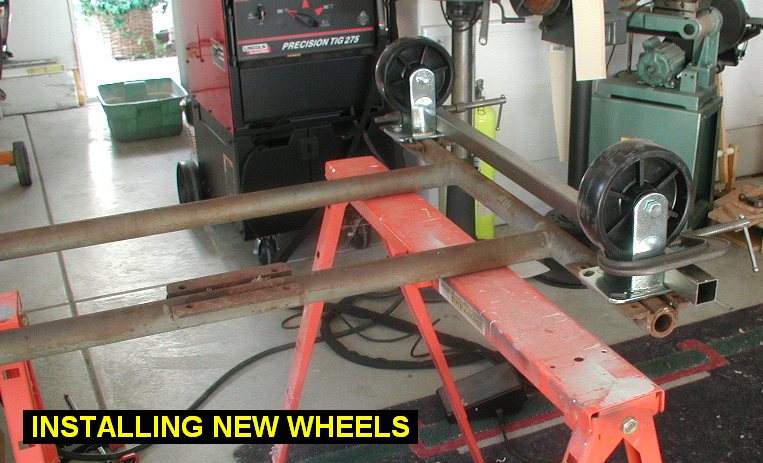
| 09/26/08 |
4.5 |
1007.5 |
Located and milled the holes for the lower
bungs that go in at the 6 degree angle. Using the motor mount and the
plate I used to jig up the fuselage, I tack welded the bungs into the
uprights. I then used an angle grinder to make the bottoms of the uprights
fit onto the round tubes of the base. I took off the old worn out wheels
and welded new wheels on. |
 |
 |
 |
 |
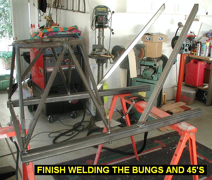
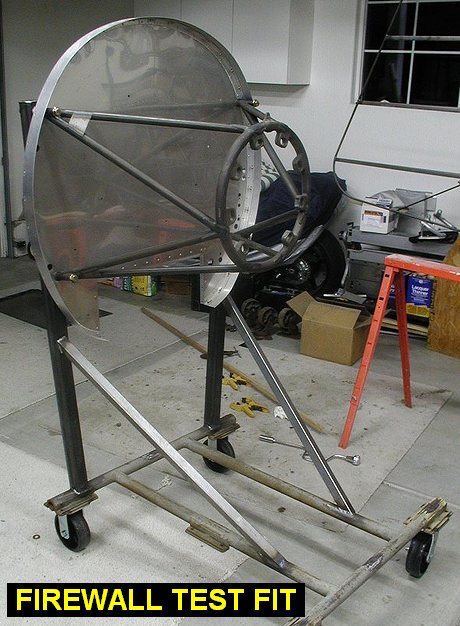
| 09/27/08 |
8.5 |
1016.0 |
Cut and fit two 45's to fit between the
uprights and the base. Tack welded them to the uprights. Cut and
tackwelded a crossmember across the top of the uprights. Ground the rest
of the old tube welds off the base. Welded up the bungs and the 454's at
the uprights. Located and tackwelded the upright/45 structure onto the
rolling base, then finish welded it. Welded two caps on top of the
uprights. Test fit with firewall and motor mount looks good. Ready for
sanding and painting. |
 |
 |
 |
 |
| QTR TOTAL |
29.1 |
|
|
3RD QTR 2008
|
•
•
•
|