| 4TH QTR 2000 |
 •
•
 •
•
 •
•

|
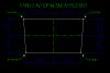
| 10/02/00 - 2.0 hrs Added extra crossmembers to table frame, now crossmembers 24"O.C. Installed lower shelf then table top, both are 3/4" Sturdi-Floor plywood. Painted the top white to see layout lines better and reflect light.
| |
| 10/13/00 - 4.0 hrs Unpacked and rust proofed with RustLick 631 the laser cut and pre-bent fittings & other sheet metal parts received from Kimball Enterprises. The parts look great and will save a bazillion hours of work. I cannot see any logic to making these parts from scratch!!! I've tried to number the parts in the pics for those of you with plans. I spent quite a bit of time comparing the parts to the plans, and visualizing their location and installation. I also had Kevin Kimball make the engine mount bungs and weld them into the 1.25" dia tubes for me. Since I am building my fuselage as top & bottom first (compared to sides) he also was able to drill the holes for the landing gear mount tubes. Moved table to work site and leveled it using a water level along with a Smart Level. I used a dial caliper to measure water height in 2 identical glasses, I quit when I got it within .020" over 16 feet! Later, I'll trim and glue the shims together to the legs.
| |
| 10/14/00 - 0.8 hrs Drew centerline on table: I cut two small notches at each end of table, ran a tightly stretched piece of .020 Stainless steel safety wire. I then marked the table along the wire in several places with a sharp pencil and then used a straight edge to draw the center line. | |
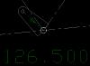
| 10/15/00 - 1.0 hrs Layout work, located crossmember STA locations along centerline using 36" stainless steel rule graduated to 1/100th of an inch. Also drew some crossmember centerlines perpendicular to centerline, using compass arc technique (shown in second picture) to ensure squareness.
| |
| 10/16/00 - 2.0 hrs Finished layout of bottom ladder. Used jeweler's 15x loop, and a very sharp pencil to keep accuracy as high as possible at this point. Chainsaws and sledge hammers on the way.....
| |
| 10/20/00 - 1.5 hrs Since the fuselage uses various tube diameters, and the largest tube is 1.25" shims are needed to keep all the tube centerlines 0.625" above the table. So today I cut shims out of 1x2 poplar, using the chop saw. After some trial & error, I was able to get them accurate to � .003". Shims as follows: 1/16", 1/8", 3/16", 1/4", 5/16" & 3/8". Since I have no idea how many I'll need I made bunch, and they went pretty fast once the stop was set for each thickness.
| |
| 10/25/00 - 2.0 hrs Worked on making blocks to keep tubes in position on the table. Used the drill press to drill 2 holes per block. Gilly was a good drill press operator, although she got bored after awhile. | |
| 10/29/00 to 11/02/00 - 6.3 hrs Made a rack with 20 dividers to hold the 4130 tubing on the bottom shelf of the table. Finished drilling the rest of the blocks. After that l started cleaning & sorting the tubing. Also, I've been wiping it down with the rustlick.
| |
| 11/04/00 to 11/05/00 - 2.0 hrs Made a Fishmouth Cutting Guide for the metal cut-off saw, by welding a section of 1" square tubing onto a plate that bolts to the saw base. Also received pre-bent tail tubing and the motor mount from Kimball Ent.
| |
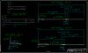
| 11/06/00 - 3.0 hrs Got a stupid field standby assignment where I had to drive 1:45 out to the airport and loiter for 4 hours waiting to be assigned a trip (never happened). So I took the laptop and worked on the fuselage control system analysis, which is basically a CAD drawing of the system. First I draw an item on the plans fuselage then I draw it on my short fuselage, to see if any dimensions need adjustment with the shorter fuselage.
| |
| 11/08/00 - 3.0 hrs After various emails with Kevin Kimball regarding the landing gear attach holes and their location on the bungs, I decided to re-draw location of bungs in longerons, and also draw longerons to determine length. CAD is such a powerful tool, being able to draw anything full scale in the computer makes actual construction easier.
| |
| 11/08/00 - 2.0 hrs Documentation. Redesigned website to make things easier to find, and not buried so deep, especially the build log. More consistent use of color. Updated the MessageBase file with the latest information on building, and edited it for www use. Uploaded it it to site. | |
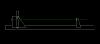
| 11/14/00 - 2.2 hrs Cut fishmouths on 4 longeron tubes, 7/8"x.058 splice tubes, and 1.25"x.120 bung tube stock. Bung stock is for practice welding before welding bungs to longerons. In picture note blue masking tape was used to keep both cuts at same location for symmetrical fishmouth.
| |
| 11/16/00 - 1.5 hrs Cut 1" diameter longeron tubes to correct length, after inserting into Bungs and locating front face of bung .625" ahead of STA 0.0
| |
| 11/17/00 - 2.5 hrs Finshed cutting 4 splice tubes (210-78), and some practice stock. Practice welded a 1.00-.875-.75 fishmouth splice. It wasn't pretty, but I did get good penetration. Setup: 1/16 2% Thoriated Tungsten and Collet Body, #6 Cup, 15cfm Argon flow, full throttle set at 110 amps, but probably didn't go above 40 amps. More practice!
| |
| 11/18/00 - 2.0 hrs Drilled .75" diameter holes for LG attach in lower longerons to match ones in lower bungs. | |
| 11/20/00 - 1.0 hrs Another practice fishmouth weld. Better, but I'll practice more. | |
| 11/21/00 - 2.0 hrs Cut more pieces for fishmouth welding practice. Also cut oak blocks to width of various tubing diameters �.004 and drew centerlines on them. I will use the oak blocks to locate jig blocks along tubing centerlines on table layout.
| |
| 11/25/00 - 1.0 hrs Cleaned up the LG attach holes in the 1" longerons with a round file, then tack welded the lower right longeron together. | |
| 11/26/00 - 0.7 hrs Tacked the lower left longeron. Kevin says not to worry about the 'star look' in the welds. It is a factor of temp, I got it slightly hot. If done right with the ER80S-D2 rod, the weld will have golden to copper color streaks in it. A little too hot and it gets the stars.
| |
| 12/02/00 - 2.0 hrs Welding an upper longeron together. Still need to weld the bung (torch cable too short) | |
| 12/03/00 - 2.0 hrs More welding on the other upper longeron.
| |
| 12/15/00 to 12/18/00 - 4.5 hrs After much welding, the longerons are now ready for fitting of crossmembers etc. Also I am now using a 100 amp, 25 ft. highly flexible cable, flex head TIG torch from Hi-TechWelding. It works great and the super flex cable seems to allow much more freedom while welding, which is always helpful when welding tubes.
| |
| 12/20/00 - 1.0 hrs Figured out how Bud Clark's Rudder & Brake Pedal Jigs work, and labeled them for easier use. Also welded some beads on the post that holds 510-61 since the tube fit so loose. I just ground the beads down equally until the .500x.035 tube fit snug.
| |
| 12/21/00 - 2.0 hrs Took my cut list over to Ken's shop and used his lathe to part off the required lengths for the rudder and brake pedals.
| |
| 12/22/00 to 12/26/00 - 1.6 hrs Cut the 510-58 tubes down to size then fit them to the 510-60 and 510-61 with the bench grinder. | |
| 12/28/00 - 2.0 hrs Cut and notched the 510-58 tubes for the rudder pedals. Discovered that using cut list taken from the parts list has 510-54, 510-55 & 510-61 now cut to wrong dimensions, compared to actual drawings. | |
| 12/29/00 to 12/30/00 Got an all expenses paid trip to Orlando, FL to visit Kimball Enterprises for a day, plus I even got to fly the jet there myself. Thanks United! Ok, so I had to rent a car and fork over several pounds of quarters to drive on Florida's fine toll roads, but I was able to spend a solid day just hanging out with Kevin and Bud Clark, talking about the 12. Also, I was able to take 268 pictures of the Model 12 in various stages of construction before time and batteries ran out. Kevin also gave Bud and I a TIG welding demonstration so we could observe his technique. I learned a lot from this, he can flow a bead like he's got a caulking gun.
| |
| 12/31/00 - 1.5 hrs Welding practice after observing Kevin. I was using too little amps, which slowed down my travel speed causing the work to get too hot. Also, I had not been keeping the tip of the rod inside the argon zone, which keeps it clean while welding. Here's a sample of my latest progress, which is better looking now.
| |
| Quarter Total 57.1 hrs / TTD 96.9 hrs | |
| 4TH QTR 2000 |
•
•
•
|