| 1ST QTR 2001 |
 •
•
 •
•
 •
•

|
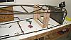
| 01/01/01 - 1.0 Drilled the 5/8" holes in the rudder pedal parts 510-56. When I cut parts 510-54 and 510-55 I took the length dimensions off the parts list. As you can see, part 510-55 is too short and should be 1.63" instead of the 1.25" as listed. The brake hinge tube 510-54 was cut to 2.25" as per the parts list, but should really be slightly less than 2.12" to fit the brake pedal, so it is too tall in the picture. I learned that the drawings should be checked before cutting any metal.
| |
| 01/03/01 - 2.7 Trimmed and cut new parts on Kens lathe. Deburred all parts. Tack welded rudder and brake pedals.
| |
| 01/05/01 to 01/11/01 - 3.7 Welding brake and rudder pedals.
| |
01/12/01 to 01/15/01 2.5 106.8 Welded 510-62 AN960-10 washers on brake pedals. Also added 510-63 master cylinder upper mounts to brake pedals.
| |
| 01/18/01 - 1.7 Made fuse tubes 210: 24,25,27,29, 39 and 40 using Ken's Bridgeport milling machine. Sorry, forgot the digicam. HINDSIGHT NOTE added later: I recommend getting the aluminum landing gear sway plate from Kimballs and using it at this stage to align the longerons. It will save some hand file work later when locating the gear bushings.
| |
| 01/19/01 - 1.5 Drilled the holes in the pedals for the cotter pins, thus finishing the pedals until time for installation on fuselage.
| |
| 01/22/01 to 01/24/01 - 3.5 Set up cool mist unit on drill press, its from Enco and is Model 505-2079 and I'm using Formula "77" coolant Model 505-2076. Then worked on cutting and fitting tubes. The mist unit really saves the holesaws, by keeping them cool while they cut. It works by blowing compressed air that has a very fine mist of a water soluble (non-rusting) coolant. It runs fine on about 50 psi, all I do is open the valve, open the Bleed Screw a lot to get the coolant flowing then close it to the desired flow, then start cutting metal.
| |
| 01/25/01 - 1.5 Cut and notched crossmembers 29 & 31 the ones where the longerons get bent inward towards the tail. After fitting them for an unbent longeron, I then took .035 off the backside notch so that the longeron will have room to come in when bent. See pictures for details. Like Andy Holoubek, I dismantled my Joint Jigger and run it with clamps, so I can cut smaller angles. I also use a tool for transfering angles from the table to the joint jigger. I have no idea what its called, but it sure makes setting angles fast. Here's a pic of it.
| |
| 01/30/01 - 1.8 Well, United decided I needed to stay away for awhile so the gave me an involuntary vacation. I'd rather have August, but I don't have enough seniority! So I'll work on the project more. While I heated, my Dad bent the lower longerons at FS 48.0 and FS 75.75. Since the longerons were loose and not tacked to any crossmembers yet, I used the vertical plywood and 3/4" scrap tube to keep the Landing Gear Mount holes vertical and aligned. I've decided to bend the longerons first, and begin "stacking" the ladder from the tail and work forward. That way, I can always get the tubes in without cutting corners off them.
| |
| 01/30/01 to 01/31/01 - 8.0 After bending the longerons I started looking at the pictures I had of the tailpost area on Kevin's fuselages and discovered differences from the plans. Unlike the plans, Kevin runs all longeron C/L's tangential to the 1" tailpost, so I have redesigned my fuselage to do so also. It was a massive CAD session but, better some computer work now than after tubes are cut or welded. I'll redraw the lines on the table soon. Spreading out each longerons 3/8" is not going to be a problem, they flex that much easily. Cleaned off tail section of building table, painted out old lines. Posted all new images of CAD files including a wireframe of the fuselage to the My Mods section of my website. | |
| 02/01/01 - 3.0 Drew new lines on table, put blocks down to keep longerons in new postion. Cut longerons to rough length, with the intention of fitting to tailpost later. Made tailspring crossmember (not in plans, see Changes section) from .875 x .035 tubing and used the grinder to fit it to the longerons. Then I cut all the crossmembers and diagonals to rough length.
| |
| 02/02/01 - 3.5 Fitted all remaining crossmembers in lower fuselage ladder using the Joint Jigger (JJ) and drill press. The drill press makes it easy to control the feed of the hole saw for good cutting action. Also fitted tube 210-36. I was able to use the JJ for one cut but the other one (far right picture Joint 36 and 35) was way too acute of an angle. After 10 minutes roughing it out with the aviation snips and some fine work with the file it fit great.
| |
| 02/03/01 - 3.2 Fitted diagonal 210-34, then both diagonals 210-32. Was able to do all with the JJ. When its cranked to 22 degrees its kinda weak, since I have to run the arbor support with only one bolt instead of two. I also run 4 C-clamps on it to keep the tubing clamp steady after I noticed it creeping a little. Having the coolant spray and slow feed rate works ok though, and I was able to make all cuts today with the JJ right on with no "do-overs" also the saws are still sharp.
| |
| 02/04/01 - - We had a nice sunny day about 65� and so went riding with my friends at Club Moto instead of working on the project. I like being on vacation!
| |
| 02/05/01 to 02/08/01 - 10.5 Cutting and fitting tubes. Finished about 4pm. Only had to replace one hole saw, since I slipped and dug it in while cutting, and broke a tooth off it.
| |
| 02/08/01 to 02/09/01 - 5.2 Tack welding lower ladder. It took longer than needed probably, I wasn't sure how much tack weld was needed, so I ran a couple of short beads on each tube. It definitely won't break if I drop it!
| |
| 02/13/01 - 1.5 Removed blocks from table. Setup blocks at end of table to hold tailpost.Only needed one very thin shim to get it vertical.
| |
| 02/15/01 to - 02/18/01 133.3 Kevin told me where to put the extra .625 x .035 tube to mount the Smoke Tank Bushings. Refined AN hardware list spreadsheet file.
| |
| 02/18/01 - 2.0 Rather than paint over previous layout, I decided to draw top ladder going opposite direction, and use highlighter to out line each ladder. Just in case I need to make a ladder over again.
| |
| 02/19/01 - 1.5 Fit crossmember 210-39 to upper bungs. Cut .03 relief off aft radius of 210-40 for bending longerons. My friend Phil (another Pitts 12 builder) came over and helped me bend the longerons in at FS 22.0.
| |
| 02/20/01 - 1.7 Cut and fit crossmembers 210-41 and 210-42. Ken came over and helped me do the longeron bends at FS 86.0 | |
| 02/21/01 - 3.5 Cut and fit crossmembers 210-44, 210-46, Smoke Tank Tube and half of the 210-43 & 210-45. Trimmed longerons to not hit each other where they intersect. After I bend them up the 0.97", I'll fit them to the tailpost. | |
| 02/22/01 - 1.5 Finished fitting crossmembers 210-43, 210-45. Top ladder is now ready to be tack welded. This one went much faster. | |
| 02/26/01 - 1.3 Before fitting upper longerons to tailpost I discovered a layout error of an extra 1" between the 210-46 crossmember and the tailpost. If I had fitted them, the tailpost would have been 1" further aft. Tack welded top ladder is ok, the wild longerons at the rear are just too long. So, before continuing, I sanded off the old lines on the table and touched up with paint for re-drawing on the table. | |
| 02/27/01 - 1.5 Re-drew top ladder lines on table. Bent the upper longerons at FS 135.0 so the ends went down an inch to they can be fitted to the tailpost at .97 below longeron C/L | |
| 02/28/01 - 1.3 Worked on .100" thick steel plate to sandwich between the engine mount and longerons for assembly. It will assure the proper relationship between upper and lower ladders at the engine mount. Layout holes and drilled 2 of them to .50"
| |
| 03/01/01 - 1.5 Drilled other two holes then took it over to Kens shop and put the 6� bend in it with his power brake.
| |
| 03/04/01 - 3.6 CAD work to draw the jig boxes I'll use to locate the lower ladder above the top ladder for assembly. Got the first one partially cut. Also drew FS's for the lower ladder on the table for reference.
| |
| 03/05/01 - 3.0 Finshed one jig box and put the lower ladder up in the air, bolted to the engine mount. Had to use a .030 shim between the engine mount and one of the longerons to get the two ladders centered over each other.
| |
| 03/06/01 - 1.0 Added some 1/2" square steel vertical supports to the engine mount plate to eliminate some flex.
| |
| 03/07/01 - 4.0 It bugged me not having a perfectly straight fuse this early in the assembly, so I did some investigation. The table was still level to 0.0� so I checked the eng mount plate. Found the holes were very slightly out of symmetry, so I slotted the holes a little for the bottom ladder (one in the air) slightly with a file. This very slight shift along with a stronger eng mount plate allowed everything to line up on centerlines with no shims. I used a 3/4" block under the engine mount to assure thrust line is 0� vertical which is plumb to the table. With that settled, I then I built the remaining two jig boxes.
| |
| 03/10/01 - 3.0 Spent three hours cutting and fitting firewall vertical tubes 210-4 (the ones not labeled in the plans) what a pain fitting to those welded fishmouths! There's some gaps in the fit since I had to do some freehand with the cutoff tool, but they should weld up ok.
| |
| 03/11/01 - 2.8 Made a temporary jig board with blocks to make the firewall diagonals 210-50 and fuel pump mount 210-85. Cut and fit the diagonals, then tack welded the verts and diags in at the firewall.
| |
| 03/14/01 - 1.5 Cut and fit the 210-85 fuel pump mount. I didn't tack it in yet. I can always do it later, and it might get in the way of welding later. Also worked on the 210-5 verticals. | |
| 03/15/01 - 1.8 Finished fitting the 210-5 verticals, progress is slower now because there is so much fitting to be done for each new tube. I use a string to get the angle of cut for the joint jigger, and secondary trimming is done with the 4"cutoff wheel freehand. I mark the tube with the silver marker, then grind it off. Works pretty well.
| |
| 03/16/01 - 1.7 C&F the 210-6 tubes. I still haven't made it over to Ken's yet to cut the 210-75 & 76 landing gear mount bushings from .75 x .120. Right now I'm just using scrap .75 dia thin wall tubes for fitting. I won't tack weld the gear bushing in anyway until I can use the Kimball aluminum gear sway plate to locate the gear bushings and then also make sure the gear is perfectly straight with the tailpost. I don't want the airplane to taxi crooked!
| |
| 03/19/01 - 1.8 Spent almost a couple hours fitting one of the 210-19 internal diagonals. What a lot of work. Rough cutting them was no problem, but after that the routine was: Test fit, mark small area to grind off, grind, repeat. About 15 times for one tube. Hopefully the second one will go quicker. I didn't want to grind too much off and garbage the tube, plus it was hard to see which part of what tube was interfering most of the time. I guess if it was easy, everybody would be building these things!
| |
| 03/20/01 - 2.2 Fitted the other 210-19, then worked on fitting all the tubes together at the FS 22.0 junctions. Got all fitted except one of the 210-7's on one side.
| |
| 03/23/01 - 3.0 Fitted the remaining 210-7, then tack welded tubes 210-6, 7, 19, then 5's in that order. Since I didn't have the gear bushings 210-75 & 76 yet, I only tacked the -5 and -6 tubes to the longerons, that way I can still slide the bushings in whenever I get them cut, sometime before finish welding. Before bending the bottom fuselage ladder at FS 24.9, I removed the jig box at that location. It worked well, heating the longerons and letting the ladder bend until the crossmember 210-29 sat in the jig box at FS 48. Also the plumb-bob's are still on C/L at each end, yea!
| |
| 03/25/01 - - Jumpseated to Seattle. Bob and I drove Jerry's 1 ton dump bed truck to Bonners Ferry Idaho. Loaded up a partially completed wing kit and plans (serial no. 007, the Bond Biplane!) that I bought from Tim. Drove back to Seattle, hung the spars in Jerry's barn and stashed the wings in Joann's spare bedroom for later retrieval. Flew home.
| |
| 03/27/01 - 1.5 C&F tubes 210-8. I don't know if it matters much, but as much as possible, I try to allow the .049 wall tubes to go all the way to the .049 longerons. Then I trim the .035 tubes to fit the thicker tubes. Also, I'll tack the -8 tubes in after fitting the -9 tubes. Its easier to fit the -9's to the longerons without the -8's in place, then put the -8s back in and trim the -9s to fit again. And no, the tubes aren't bent, that's just the wide angle of my camera!
| |
| 03/28/01 - 3.1 C&F tubes 210-9. Tack welded the -8 and -9 tubes in, then removed that jig box. Phil helped me do the bend in the bottom ladder at FS 48.0
| |
| 03/29/01 - 1.0 Worked a little on the 210-10 tubes, they still need final fitting.
| |
| 03/30/01 - 3.2 Finshed fitting the -10 tubes. C&F the 210-11 tubes. Tack welded them in, then removed the jig box there. Now ready for bending at FS 75.75 (plans 80.75) bottom rear seat. See detail pic at right to see gap left at rear of joint to allow for bending of longeron. CAD work to determine height of three next jigs going back to tail. Note also the "blacked out" part of the images is to reduce file size only.
| |
| 03/31/01 - 1.1 Made 3 more jig boxes for each of the remaining crossmembers back to the tail. | |
| Quarter Total 91.7 hrs / TTD 188.6 hrs | |
| 1ST QTR 2001 |
•
•
•
|