

| 4TH QTR 2001 |
 •
•
 •
•
 •
•

|
| 10/01/01 - 2.5 Welded the 330-7 (same as 200-79) bushing and 330-11 V-spacer onto the vertical fin. Then welded the 330-9 collar on the fin lower aft spar after setting fin & rudder in place with hinges assembled.
| |
| 10/03/01 - 1.8 Drew layout of horizontal stabilizer and set blocks on table using it.
| |
| 10/04/01 - 2.5 Tack welded one stabilizer half (except for the trim tube bushings which will go in last) and got the second set of tubes in the blocks ready to tack weld. | |
| 10/05/01 - 3.0 Tack welded the other half. Cut the 310-3 & 310-19 splice tubes, and got the 310-12 bushings deburred. Worked on finish welding the stab ribs.
| |
| 10/07/01 - 1.5 Welding on the stabilizer ribs. Also spent some time examining the laser cut cabane fittings and trying to figure out how they will be installed on the fuselage.
| |
| 10/08/01 - 1.8 Finished welding the stabilizer ribs. Set blocks to join stabilizers when ready. Worked on parts for making jigs to mount cabane fittings. The hard thing about making the jigs will be not being able to weld near Jimmy's fuselage so to not melt his powder paint. | |
| 10/10/01 - 3.0 Bought some square tube steel and angle iron for making jigs for attaching the rear Cabane Fittings. Cut some parts for the jigs. Went to Jimmy Kilroy's shop to take some measurements on his fuselage.
| |
| 10/11/01 - 2.2 Drilled holes in the angle iron parts to hold the aft cabane fittings.
| |
| 10/12/01 - 1.0 Milled out parts for the jigs over at Ken's.
| |
| 10/14/01 - 1.0 Worked on jigs, welded some parts together so that any tack welding done at Jimmy's will be away from his fuselage.
| |
| 10/16/01 - 2.6 Worked on jigs, welded the 310-16 rings to the 310-15 center elevator hinge bracket.
| |
| 10/17/01 - 0.7 Assembled last stab hinge and tack welded the V-block and Bushing in the stab spar.
| |
| 10/19/01 - 2.0 I borrowed Phil's 310-15 and bolted it to my 310-15 so that I could tack weld it on to the 310-3 Spar Splice. After removing Phil's part, I welded it up. I then figured out what bushings to use along with a 1/4 bolt and bushings to hold it when it's time to weld the spar splice. Also I worked on fitting the 310-11 tab actuator tube bushings in the ribs so the trim tubes will rotate smoothly.
| |
| 10/22/01 - 3.7 Tacked, then bent using Phil's as a guide, then welded the 210-99 rudder travel limiter. Cut some tubes for the 320-4 elevator horn tubes and the 310-21 trim tubes. Tack welded the elevator horns on their -4 tubes. Welded both of the stabilizer hinge bushings and V-blocks.
| |
| 10/23/01 - 2.4 Welded the tab actuator tube bushings 310-11, then reamed them out so the trim shafts fit using an adjustable reamer so that the trim shaft rotates smoothly but without slop. I welded the inner bushings and reamed them first before the outers, so I could then slide the shafts thru the inner bushings to keep the outer bushings aligned when welding. Also once you have the stab halves welded together and the bushings in too, you cannot put in or take out the shafts, so make sure the shafts are in before you weld the stab together!
| |
| 10/24/01 - 1.0 Welded the elevator horns on the sleeves, then used an adjustable reamer to allow the elevator spars to fit again.
| |
| 10/26/01 - 2.2 Somehow I got the 310-11 bushings a little over 2.70 apart when I tacked them in so I just made another 510-32 bushing a little longer to match. I then drilled the #13 holes through the -32 bushing and the 310-21 trim shafts. Next I welded up the 510-31 stab trim horn and 510-32 bushing and reamed it out so it would fit on the tubes again. Note that the horn gets Aligned As Shown Here with the two trim arms. I also tack welded the stab halves together AFTER inserting the 310-21 shafts.
| |
| 10/29/01 - 0.8 Welded the stabilizer splices. | |
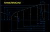
| 10/30/01 - 0.5 Discovered future problem fitting the tail fairing. Since my longerons are spread apart a little more at the tail post, they are no longer parallel with the inner stab ribs. The tail fairing may need some custom work to fit between the longerons and the ribs, or some alternative solution may have to be found. No big deal thanks to advice from Kevin. To avoid this problem when building one of my short fuselages: SEE MY REVISED STAB DRAWING
| |
| 10/31/01 - 1.0 Tack welded the 310-12 bushings on the forward spar of the stab. I tack welded them with the stab shimmed flat on the table, and the bushings sitting on a .063 plate. With my shim setup on the table, my tube centerlines are .625 above the table. The .063 plate puts the C/L of the bushing at the same height. I left the aft ones off for now because the .70 dimension shown for them will not work on my fuselage since my longerons are further apart. I'll set them to match my fuselage. | |
| 11/01/01 - 4.5 Aligned and set stabilizer to 2.0 degrees incidence, then tack welded the forward 210-79 fuselage bushings. I then marked the proper location of aft 310-12 stab bushings to fit the aft fuselage longerons. I tack welded them to the stab with the stab flat on the table, and the bushings sitting on a .063 plate to set them at the right height. I then remounted the stab on the fuse, rechecked alignment and incidence, then tack welded the aft 210-79 fuselage bushings in. Then I spent almost three hours welding all the 8 bushings. The aft ones on the fuselage were kinda hard to get to and made welding slow.
| |
| 11/06/01 - 2.5 Adjusted bends on the 210-6 tail strut fittings. Aligned and tacked welded them onto the fuselage at FS 146.5. Used the oxy-acetylene torch to heat them up and a small hammer to shape then around the crossmember there. Then finished welding them up. Fit stabilizer and leveled it so the outer stab bushings can be re-tacked in the proper locations for my short version fuselage, since having them at 32.0 from stab C/L isnt far enough out to meet the struts.
| |
| 11/07/01 - 2.1 I flattened the bottom ends of the struts in the vise with some 1/8" sheet metal in the slot. I then mounted and leveled the stabilizer, and bolted the struts onto the fuselage fittings. Since my short fuselage is slightly different than Kevins version, the struts I bought from him don't line up with the 310-13 bushings if installed per plans at 32.0 inches out from airplane C/L. To allow for this difference I clamped the struts in their proper location to the forward stab spar, double checked the stabilizer level, then marked on the spar where the bushings should go, which ended up being about 1/8" further out. I then welded the bushings, and drilled the 3/16 holes in the upper strut ends.
| |
| 11/09/01 - 1.5 Welded the 310-22 arms on the trim tube shafts.
| |
| 11/10/01 - 3.0 Went over to Jimmy's and tack welded the cabane fitting jigs to fit his fuselage (a Kimball HP fuselage). Later that day I accidentally stripped out the threads of the upper left engine mount bushing (bung) ouch !!! I thought my fuselage was scrap. I don't consider repair time to count as construction, so the subject is covered separately elsewhere. Here's the whole story
| |
| 11/12/01 - 2.8 I tack welded both elevators together except for the trim tab channel and short rib. I also added a 1/4 -.035 tube to keep fabric from pulling the 320-7 tube in. The horn assemblies are not welded in yet, since they would keep the elevator from laying flat on the table. Instead I used a short section of 1" x .049 tube in its place for fitting the 320-7 trailing edge. I'll tack weld the horns and -7 TE on when the elevators are installed on the fuselage.
| |
| 11/20/01 - 2.7 Adjusted the angles on the 320-15 channels to 45 degrees per plans. Fitted and tackwelded the channels and 320-9 short ribs in.
| |
| 11/24/01 - 2.0 Welding the elevators. Adding braces to cabane jigs. | |
| 11/25/01 - 2.2 Welding the elevators. Adding braces to cabane jigs. | |
| 11/26/01 - 1.0 More welding on the elevators. United called and interrupted my progress by sending me out to cover a trip for some other Captain that lives in DEN but flies out of SFO and couldn't get himself to work. I really don't like it when commuters don't make their trips, especially when I'm the guy that gets to race out to the airport to save the departure.
| |
| 11/28/01 - 1.8 Drilled the rosette holes in the elevator horn tubes. Made the 320-22 elevator spacer out of 1/2x1/2 aluminum.
| |
| 11/29/01 - 1.5 Went over to Kens and cut a couple of .080 spacers out of 7/8" tube to move the elevators outboard inside the horn tubes, so they fair better with the stabilizer out at the tips. The spacers wil get inserted inside the elevators before sliding on the KP4 bearing. Set up the elevators in a faired position and then tackwelded the elevator horns on at a 70 degree angle.
| |
| 11/30/01 - 3.3 Used the gas torch and small hammer to heat and form the elevator spar tube ends to meet the 3/8 trailing edge. Made small caps of from sheet, then welded the tips. Also welded the elevator horns and rosettes. Located and welded the 320-21 hinge collars (.25 wide).
| |
| 12/01/01 - 2.0 Finished adding braces and welding the cabane jigs.
| |
| 12/02/01 - 1.7 Bent the 510-27 trim tab rods 15 degrees (don't bend to plans drawing its 30) then assembled tabs onto elevators and faired everything. Marked tubes for cutting.
| |
| 12/03/01 - 2.2 Reaffirmed trim rod lengths. NOTE: If you are building HP elevators using Kevins pre-bent tubes, you need to make your trim tubes about 1"shorter, exact length determined by lining everything up yourself. Cut to length and put fishmouths in using air cutoff wheel. Removed cadmium plating from rod ends using pool acid. Welded rod ends onto tubes. The first weld wasn't pretty, but then I switched from 1/16" welding rod down to smaller .045 rod, which worked great. That night I got out my lathe cut parts for the bearing cages and sorted them to minimize time spent sizing them at the disk sander. Proper dimensions are critical for smooth control operation, see BearingCagesDrawing.
| |
| 12/04/01 - 2.2 Sized and deburred bearing cage sets. Test fit each set with actual bearings to make sure the outer races were not being pinched. When bolted together, the middle spacer should be free to drop as shown, but with very little end play.
| |
| 12/05/01 - 2.5 Did the rosette welds on all the bearing cages. Some CAD work verifying the changes I've made to the elevator control system, before starting to make parts for it. | |
| 12/07/01 - 5.5 Went over to Jimmy's and took measurements of his elevator control system and fuselage to compare to my design, mostly to make sure I haven't forgotten anything. Found my fuselage very similar, but 1/2" longer overall, with some very minor differences in some crossmember locations. Also took measurements of tab locations. That night, using my Torque Tube Drawing, I cut the big sections out of the torque tube blank freehand with the cutoff tool. Then I welded the .063 and .125 hole doublers on the towers and welded up the bottom of the rear stick. In bed at 0120.
| |
| 12/08/01 - 2.0 Rigged up a straight section of 1/4" all thread, 3/8" tubing and various numbers of washers and nuts to hold the forward stick tower and the aft bearing support at the proper 23.10 spacing and to keep the bearings in alignment. Then tack welded them to the torque tube.
| |
| 12/10/01 - 2.8 The bearing cages are supposed to be 23.10 on center when installed on the fuselage and the torque tube. I cut a section of 1" dia. tube to 20.85 so that when one of the bearing cages has a weld plug (.375 sticks out) inserted instead of bearings, the tube will keep the bearing cages at the proper spacing and alignment. I then assembled the tube and cages with bearings in the front cage and plugs in the rear cage, and the spacer tube held tight with a long 1/4" threaded rod. After clamping it to the fuselage in the proper position, I welded the AFT bearing cage in. After it cooled, I reassembled the tube, this time with bearings in the newly welded rear cage and weld plugs in the front cage. I then welded the front cage up. I suppose there might be simpler ways to do this, but this went pretty fast and the torque tube swings nice and free with no slop or binding.
| |
| 12/11/01 - 2.0 Welded the forward stick tower and aft bearing support. Located and welded the rear stick tower on the torque tube.
| |
| 12/18/01 - 4.0 Bent the 510-14 plates out of the way so I could weld on the rear stick. I should have welded the stick to the bearing cage FIRST. Anyway, after welding the stick on, I bent the plates back and tacked them down. Then I heated and hammered the plates to mold around the tube, then I welded them up. After cleaning up the bearing holes so the bearings would slip in again after welding, I then welded the AN315-5 nuts onto the stick towers. I welded the 510-9 aileron bracket on the torque tube before going to bed at 0100.
| |
| 12/19/01 - 2.7 Cut, fit and tack welded the aft seatback tubes
| |
| 12/23/01 - 2.6 Welded the aft seatback tubes, then tacked in the rear idler tabs 210-48. | |
| 12/26/01 - 2.8 Tacked in the front idler tabs 210-48. Cut and welded the 510-44 tubes on the idlers. I left them a little long and will trim them later before welding the rod ends. Welded the idler brackets on both sides, since I saw pictures of Kevin's fuselages with same.
| |
| Quarter Total 97.5 hrs / TTD 381.1 hrs | |
| 4TH QTR 2001 |
•
•
•
|


