|
2ND QTR 2006
|
 •
•
 •
•
 •
•

|
| DATE |
HRS |
TTD |
ACTION |
IMAGES |
| 04/18/06 |
3.2 |
883.9 |
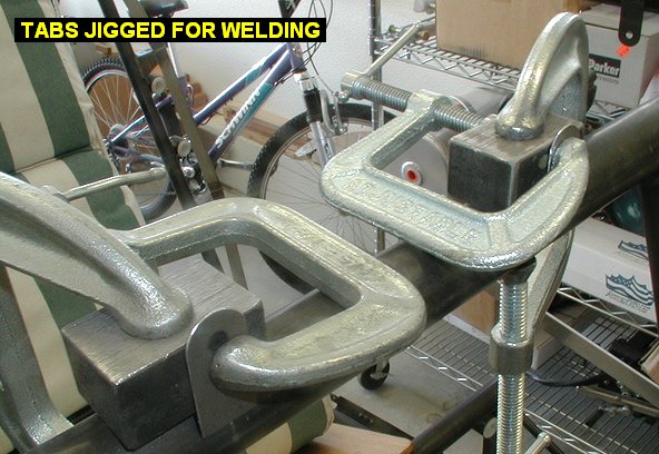
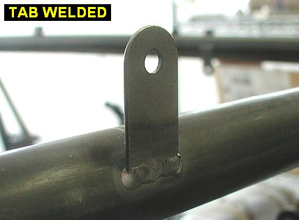
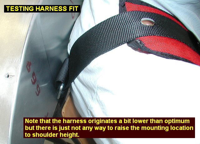
Welded in the
mounting tabs for the passenger headrest panel onto the crossmember. Cut
out areas in the panel for the shoulder harnesses to exit their attachment
to the crossmember tube. Since my panel is a little bit forward compared
to a standard panel, I had to make the cutouts taller. The amount of
cutout was determined by sitting in the front seat and testing the
shoulder harness fit. |
 |
 |
 |
 |
| 05/07/06 |
3.5 |
887.4 |
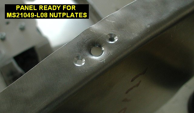
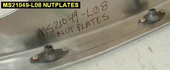
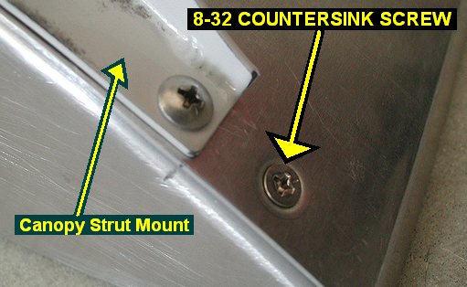
Installed MS21049-L08
countersink nutplates in both panels so I can use 8-32 countersink screws
to hold the top cover down. I used a set of springback dimple dies from
Avery Tools to dimple the panels and cover. Note that standard
non-countersink screws and rivets are used to hold the lift strut
attachment. |
 |
 |
 |
| 06/01/06 |
0.8 |
888.2 |
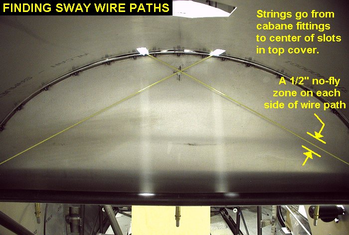
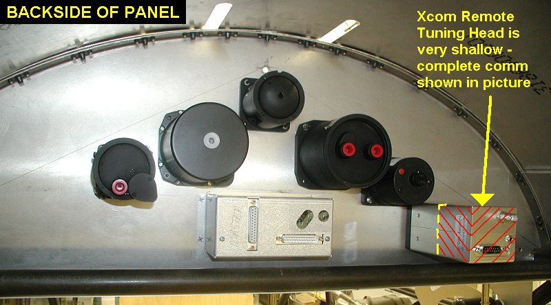
Installed the front windshield,
front instrument panel and top sheetmetal so I could determine where the
sway wires would be going behind the front instrument panel. Obviously I
cannot put instruments where they will hit the wires behind, so the big
front panel gets kind of limited as to where to put things. I ran some
string from the fuselage fittings out the center of the slots cut in the
top cover and made some marks on the back of the instrument panel. |
 |
| 06/27/06 |
2.5 |
890.7 |
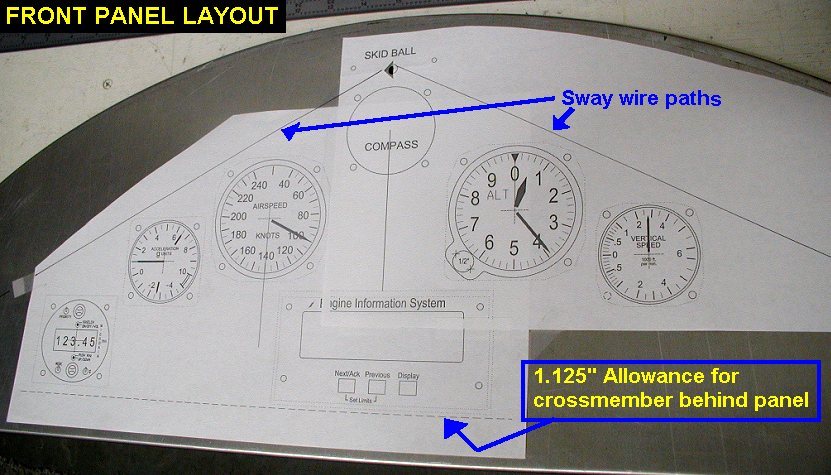
Did some CAD work on the layout
of the front instrument panel, allowing a 1/2" of "no fly"
zone on either side of the sway wire paths. I then plotted out the
instrument panel layout and taped it to the panel to see how it looks. The
compass is set higher than the arc of the others so I can see it from the
back seat if nobody is up there to read it for me. I tried to keep the
layout as close to the rear instrument panel as possible for consistency. Click
here to see my panel layout plan. |
 |
 |
| 06/28/06 |
1.0 |
891.7 |
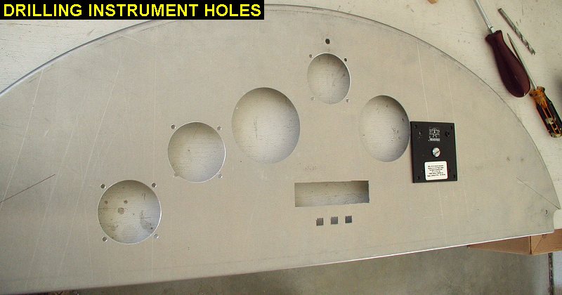
Over at Ken's to punch holes.
Since the Whitney punch press requires us to have the panel flat on the
table, working from the back of the panel, I drilled small 3/32 holes
through the centers of the instrument locations so we could locate the
punch each time. The punch has a small centerpoint that can be set into
the hole to line it up before punching the hole. I'm waiting for my front
panel vents to arrive so I'll punch those holes later. We used some small
square punches to do the EIS holes. |
| 06/30/06 |
3.3 |
895.0 |
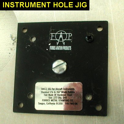
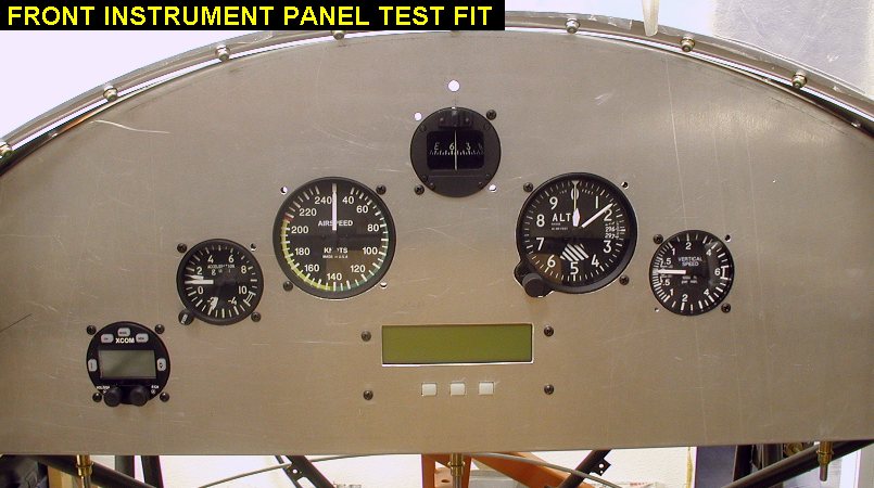
Fit instruments to
the front panel. First I used the instrument jig and drilled the needed
holes for each instrument, then I used a file to make the instrument hole
slightly bigger. When I punched the holes, they were exactly 2.25 and
3.125, and the holes need to be bigger to allow for paint on the panel and
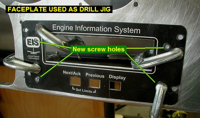
easy installation. I then used the old EIS
faceplate I had laying around to use for a template to fit the EIS.
Note that the pictures show an Xcom comm in the front panel, but I only
used it as a test, I will be putting an Xcom remote tuning head there
instead. |
 |
 |
 |
 |
| QTR TOTAL |
14.3 |
|
|
2ND QTR 2006
|
•
•
•
|


