


Plans Changes
Here's a list of changes, errors on the plans, things that the Kimball's have improved upon and a few tips to consider when building your own fuselage. Use this list at your own risk, and consider each item carefully before you decide to incorporate it into your project.


Section 210 - Fuselage Weldment
1) When building ALL LONGERONS, position the 210-77 Engine Mount Bushings so that the front face of the bushing is 0.625" FORWARD of the FS 0.00 line. This will move the landing gear attachments forward a little so the Rear Landing Gear Mount Bushing 210-76 is truly centered on the crossmembers at FS 9.00.
2) On page 1 the vertical upright tube at FS 0.0 to FS 0.0 is part number 210-4, but doesn't have a circled number depiction.
3) Idler mounting brackets 210-48 make a total of four of them, but:
Make 2 with a 0.375" radius half circle for the back of the rear seat tube.
- Also make 2 with a 0.25" radius on the half circle to fit tube 210-35 for the rear idler mounting.
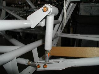
4) If planning lower profile belly formers, you'll have to change the forward idler location like on Kevins short fuselage. It is also tilted up to make the pushrods stay between the crossmember and the belly formers. Belly formers in plans are at 4" below tube C/L, while Kimball HP Fuselage uses 3" thus needing more clearance as shown below. The forward idler itself is same as plans. Also, the 210-67 tube that the idler brackets are welded on is 1/2" lower than plans.

5) Make 4 of the 210-47 Bearing Cages, 2 for the Torque Tube, and 2 for the idlers to be made from.
6) On page 3 lower left corner, the rear seat frame detail doesn't label the 210-79 bushing for the extra seatbelt mount.
7) On page 2 the Stringer Standoff location dimensions are drawn inconsistently:
- The FS102.5 & 113.0 cross-section are dimensioned at 7.50 & 7.57. Locate the standoffs 7.00" & 7.00" measured STRAIGHT DOWN from the top longeron C/L. The dimensions shown on the plans are "in plane" with the cross-section.
- The FS126.5 & 140.0 cross-section are dimensioned at 7.97 & 7.40. Locate the standoffs 7.00" & 7.00" measured STRAIGHT DOWN from the top longeron C/L. The dimensions shown on the plans are "in plane" with the cross-section.
- This applies to the other sections as well. Measuring STRAIGHT DOWN from longeron C/L will keep stringers consistent down the fuselage.
8) The plans on page 1 show a
dimension of .250 where the LOWER longerons meet the 210-20 tailpost. Also they
show a dimension of .500 where the UPPER longerons meet the tailpost which is a
1.00x.035 tube. Per Kevin, it is better to make both of these dimensions
1.00, which is longeron centerline tangential to the tailpost. This makes it
easier to weld the clusters there top and bottom, although the main reason is to
widen the joint, making it a bit more stable. Heat and blacksmith the
outer ends of the longerons to blend into the tail post.
9) Add a .875 x .058 tube to the bottom fuselage ladder to act
as a Tail Spring crossmember.

10) Add a .75 x .035 tube as shown to the BOTTOM fuselage ladder to mount the header tank.
11) I added a .625 x .035 tube to the TOP fuselage ladder to mount the smoke tank like Kevin does on his short fuselages. If you are building a plans length fuselage (169") this won't work as shown below. My crossmember at FS 110.5 is not per plans.

12) The 210-22 Tailspring Tube doesn't stick out at far as the plans say. The tube needs to be trimmed to a finished length of 1" aft of the fin post tube. In other words, 1" of the spring mount tube hangs off the end not several inches as the plans show it. This will move the tail spring and its mounting holes forward.
13) Omit the 210-51 bushing at the firewall, unless you plan on installing a Lycoming.
14) The 330-11 "V" shaped hinge support is missing from the tailpost detail. Also the support should have a slightly different angle:

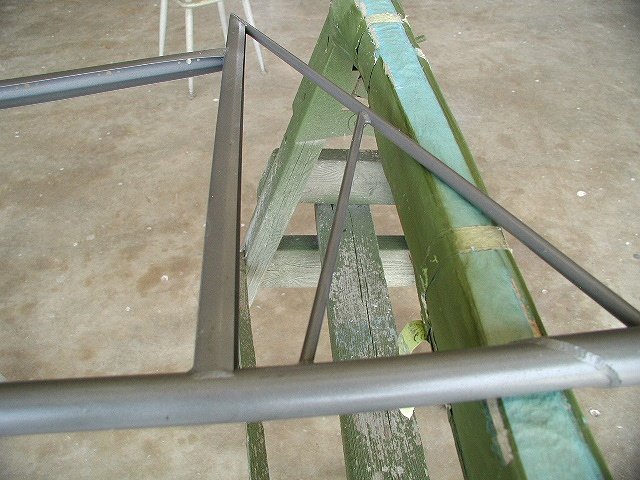
15) Be careful when doing the layout for the -86 vertical fin support assembly...the 9.63 dimension is to the top of the -88 support tube, not the top of the triangle:
16) Kevin makes some changes to the seat dimensions. The rear seat changes are because of the shortened fuselage and these dimensions should NOT be used for a plans version. The front seat changes are to recline the seat more and can be used in a plans version since Kevin's fuselage is the same as plans in this area.
17) Battery Tray: Kevin makes the 210-110 bushings 1.75 long instead of 1.00. Also, if using his laser cut -111 angles, they are 7.50 wide so you'll have to place the tubes on 8.125"centers. The -114 tray is omitted. The -111 angles are placed so there is 8.25 bteween the vertical flanges.
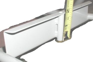
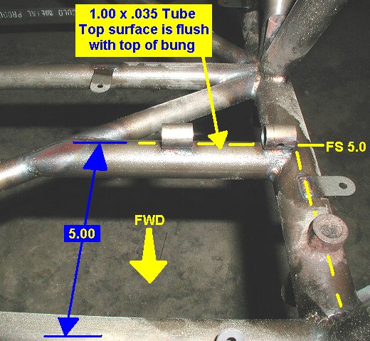
18) Kevin adds a separate tube to mount the front rudder pedals. Made of 1.00x.035, at FS 5.0 and is set with its tops surface flush with the top surface of the engine mount bung.
19) Rudder Pedal Mounts: If making a SHORT fuselage, be sure to move the rear rudder pedal mounts forward to compensate for the rear seat moving forward. Kevin puts them as shown in this image.
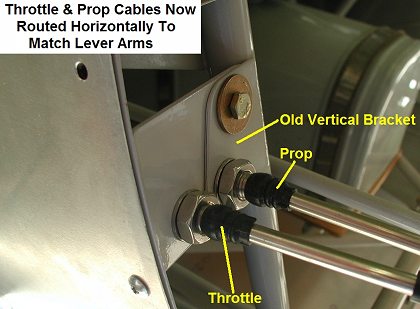
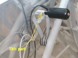
20) Throttle / Prop Cable Bracket: It is better to route the throttle and prop cables horizontally at tube 210-7. The Kimball laser cut parts include a bracket for mounting them vertical, but a plate can be added, or a new bracket can be made if scratch building your fuselage.
21) Omit the aft most bottom stringer support angles 210-62 which the plans show on tube 210-37. To see how stringers end short of that crossmember see Picture. Also the standoffs at 210-33 are 10.875 apart, and the ones at tube 210-35 are 7.375 apart, this is a bit closer together than plans.
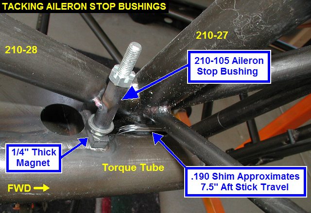
22) Aileron stop bushings 210-105 get welded on at approximately 25� not the 45� shown in the plans. Set them to hit perpendicular to the face of the torque tube. See picture.
23) Kevin mounts the 210-84 Fuel Valve Bracket 8.875" down the 210-4 tube, instead of the 9.50" shown in the plans.
24) Make the 210-20 Fin Post out of 1.00x.049 instead of the .035 wall tube as shown in the plans. The .049 tube will have a .902 inside diameter which will make a better fit for the .875 diameter 320-2 Fin Spar.
Section 252 - Landing Gear Spring
1) The 252-3 Sway Plate you from Kimball Ent. is .090 thick instead of .080 as shown in the plans.
Section 310 - Horizontal Stabilizer
1) If you get your tail tubes pre-bent from Kevin, you will get tubes 310-2 & 310-4 in .875 x .035 instead of .049 as specified in the plans. Curtis Pitts originally specified .035, but when the plans were reworked prior to Kimball Enterprises obtaining them, they were switched to .049.
Section 320 - Elevators
1) If you get your tail tubes pre-bent from Kevin, you will get tubes 320-6 bent to a tighter radius.
3) Also if you get your elevator ribs prebent from Kevin, you will find that the elevator is nearly 1" shorter in chord, measured back from the spar centerline. Kevin did this to keep the area close to plans, keeping in mind that his more square corners increase area.
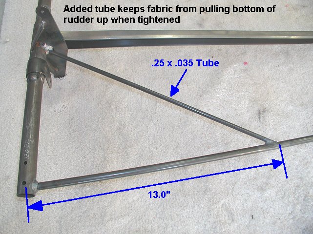
2) Also add a 1/4 x .035 or .026 tube as shown below to keep the fabric from pulling the tube in when tightening:
2) The plans don't show the 320-22 elevator spacer block that gets bolted between the two elevator horns (note the rod end bearing gets sandwiched along with 2 AN960-10L thin washers):
Section 330 - Vert Fin & Rudder
1) If you get your tail tubes pre-bent from Kevin, you will get tube 330-27 bent to a tighter radius.
2) Also add a 1/4 x .035 or .026 tube to the bottom of the rudder as shown below to keep the fabric from pulling the tube in when tightening:
3) The 330-9 collar does not have a circled "9" call out on the bottom aft fin spar where the triangle "1" note is.
Section 510 - Fuselage Control System
1) Make 4 of the 510-47, two for the torque tube, and two for the idlers.
2) 510-55 should be 1.63" long, not as listed.
3) 510-54 should be 2.12" long, not as listed.
4) 510-60, only make 4 at 2.00" long, make the other four 0.38" long.
5) The 510-62 is an AN960-10 washer.
6) Don't bother with the 510-41 tailwheel lock shown on it.
7) 510-59 only gets edge welded to the 510-60.
8) 510-61 should be 3.75" long, not as listed.
9) When cutting the 510-58, you can save 2" of material by cutting them to 3.5" before fitting, rather than 4".
10) Cut the 510-32 trim horn tube to
2.525" min, 2.55 max to allow for clearance between the hinge bushings
which are spaced 2.6 apart. The width of 510-32 tube on page 12-510-2 is wrong.
Should be 2.60 inches to match to location on the stab. The 1.57 dim
should be 1.30 & the 1.00 dim stays the same.
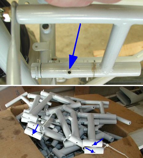
11) Drill a lubrication hole in both hinges of each rudder pedal as
shown (good eye Bud!):
12) The 510-27 trim rods, which is made of 1/2"-.035 tube, gets bent 15 degrees, not the much greater angle shown in the drawing. Use a protractor!
13) If using Kevins elevators with the shorter chord length, you'll also have to custom make the trim rods, approx 1" shorter.
14) Kevin substitutes F34-14M rod end bearings for the REPB3N shown on the plans.
15) I am using a removable front stick, which may come in handy some day if I've got to strap in some baggage in the front seat for X-C flying. Use at your own risk, this is not in the plans.
16) Kevin makes a really nice trim handle that is cut from 1/8" Aluminum.
Section 536 - Quadrant
1) Do not tap the 536-13 knob mounts, they get threaded 3/8-16 on the OUTSIDE. Then the knob screws on over it.
2) If using Kimball cover plates, note that they are identical front and aft, unlike plans. Thus the bushings for the aft plate get welded on the top side of the 210-10 diagonal. The front plate bushings get welded on the bottom of the 210-8 diagonal. Use the plates on the longerons to locate the pivot bushings.